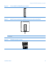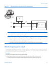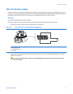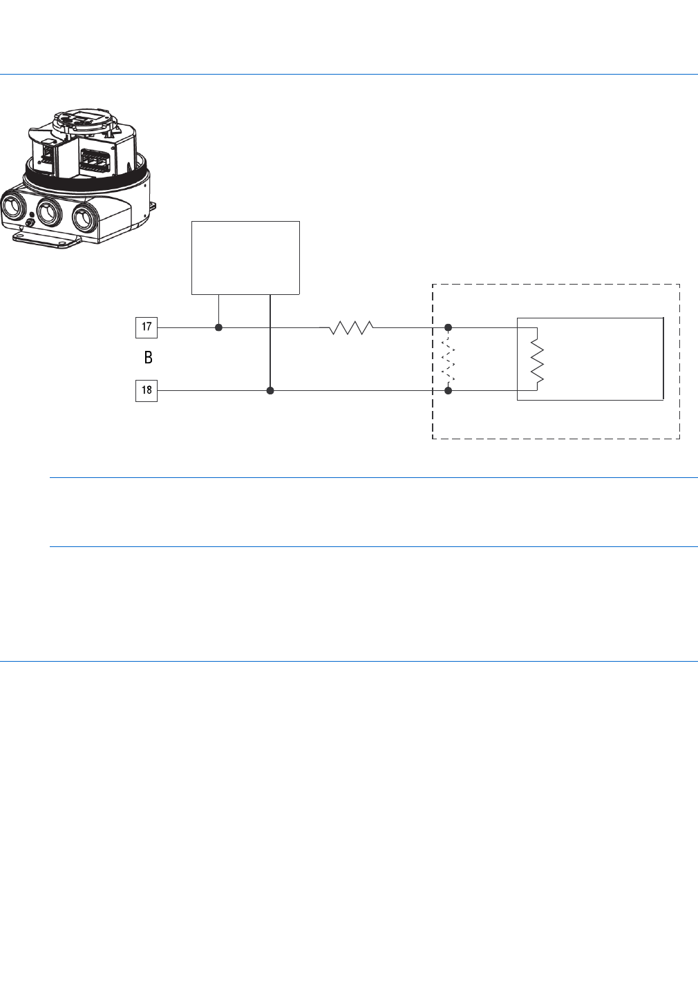
Wiringtheoutputs
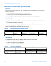
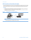
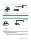
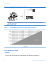
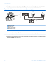
Figure 5-3 Wiring the primary mA output for HART communications
A
B
PV+
PV-
R1
R3
R2
C
17
18
A HART communications tool, ProLink II, or AMS modem
B Communicator loops or PV (Primary Variable) terminals
C DCS or PLC with internal resistor
Notes
• If necessary, add resistance in the loop by installing a resistor R1. SMART FAMILY
®
devices require a minimum loop
resistance of 250 Ω. Loop resistance must not exceed 1000 Ω, regardless of the communication setup.
• You must congure the DCS or PLC for an active milliamp signal.
• Resistor R3 is required if the DCS or PLC does not have an internal resistor.
• Ensure that mA output loops are grounded properly, either at the transmitter end or at the external device.
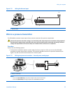
Wire the frequency/pulse output
As shipped, the frequency/pulse output of the 9739 MVD transmitter is internally powered by an isolated 15 V source via
a 2.2 kΩ pull-up resistor. This internal current is limited to approximately 7 mA. You can wire the frequency/pulse output
for increased current, constant current, or external power.
Procedure
Use terminals 15 and 16 for wiring the frequency/pulse output.
The frequency/pulse output, discrete output, and discrete input share terminal 16 as a common return.
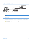
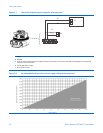
• To wire the output for the standard or default conguration (using internal power), see Figure 5-4.
InstallationManual27


