


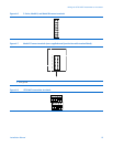
Wiringthe9739MVDtransmittertothesensor
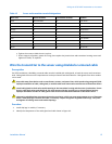
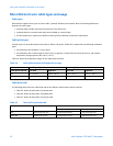
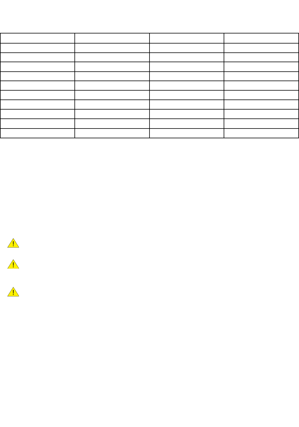
Table 4-2 Sensor and transmitter terminal designations
Wire color Sensor terminal Transmitter terminal
Function
Black
No connection
0
Drain wires
Brown
1 1
Drive +
Red
2 2
Drive −
Orange 3 3
Temperature −
Yellow
4 4
Temperature return
Green
5 5
Left pickoff +
Blue
6 6
Right pickoff +
Violet
7 7 Temperature +
Gray 8 8
Right pickoff −
White
9 9
Left pickoff −
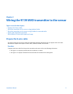
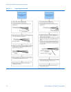
e. Tighten the screws to hold the wire in place.
f. Ensure integrity of gaskets, grease all O-rings, then replace the junction-box and transmitter housing covers and
tighten all screws, as required.
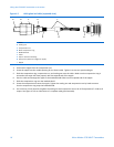
Wire the transmitter to the sensor using shielded or armored cable
Prerequisites
For ATEX installations, shielded or armored cable must be installed with cable glands, at both the sensor and transmitter
ends. Cable glands that meet ATEX requirements can be purchased from Micro Motion. Cable glands from other vendors
can be used.
Keep cable away from devices such as transformers, motors, and power lines, which produce large magnetic elds.
Improper installation of cable, cable gland, or conduit could cause inaccurate measurements or ow meter failure.
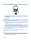
Install cable glands in the 9–wire conduit opening in the transmitter housing and the sensor junction box. Ensure
that the cable drain wires and shields do not make contact with the junction box or the transmitter housing.
Improper installation of cable or cable glands could cause inaccurate measurements or ow meter failure.
Improperly sealed housings can expose electronics to moisture, which can cause measurement error or owmeter
failure. Install drip legs in conduit and cable, if necessary. Inspect and grease all gaskets and O-rings. Fully close
and tighten all housing covers and conduit openings.
Procedure
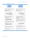
1. Install drip legs in conduit, if necessary.
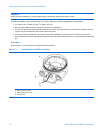
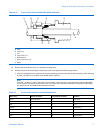
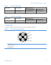
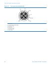
2. Identify the components of the cable gland and cable shown in Figure 4-3.
InstallationManual15