


Wiringtheoutputs
Wire the primary and secondary mA outputs
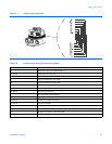
Use terminals 17 and 18 for the primary mA output. Use terminals 19 and 20 for the secondary mA output. The mA outputs
produce a user-selected 0–20 mA or 4–20 mA current. When congured as 4–20 mA outputs, the mA outputs can supply
loop-powered process indicators. The primary mA output can also be congured for HART
®
/Bell 202 communications.
Procedure
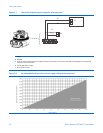
1. Determine the maximum allowable length for mA signal wiring by measuring the resistance over the signal wires
and through the receiver device. Total loop resistance must not exceed 1000 Ω.
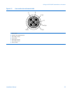
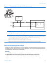
2. See Figure 5-2 for information on wiring the primary and secondary mA outputs. To wire the primary mA output
for HART/Bell 202 communications, see Figure 5-3.
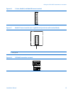
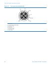
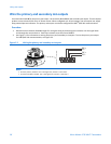
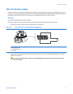
Figure 5-2 Wiring the primary and secondary mA outputs
PV +
PV -
SV +
SV -
Notes
• PV is the primary variable. PV+ is the signal line, and PV− is the return.
• SV is the secondary variable. SV+ is the signal line, and SV− is the return.
26MicroMotion9739MVDTransmitters