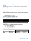
Wiringthe9739MVDtransmittertothesensor
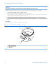
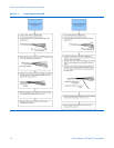
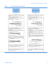
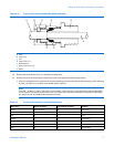
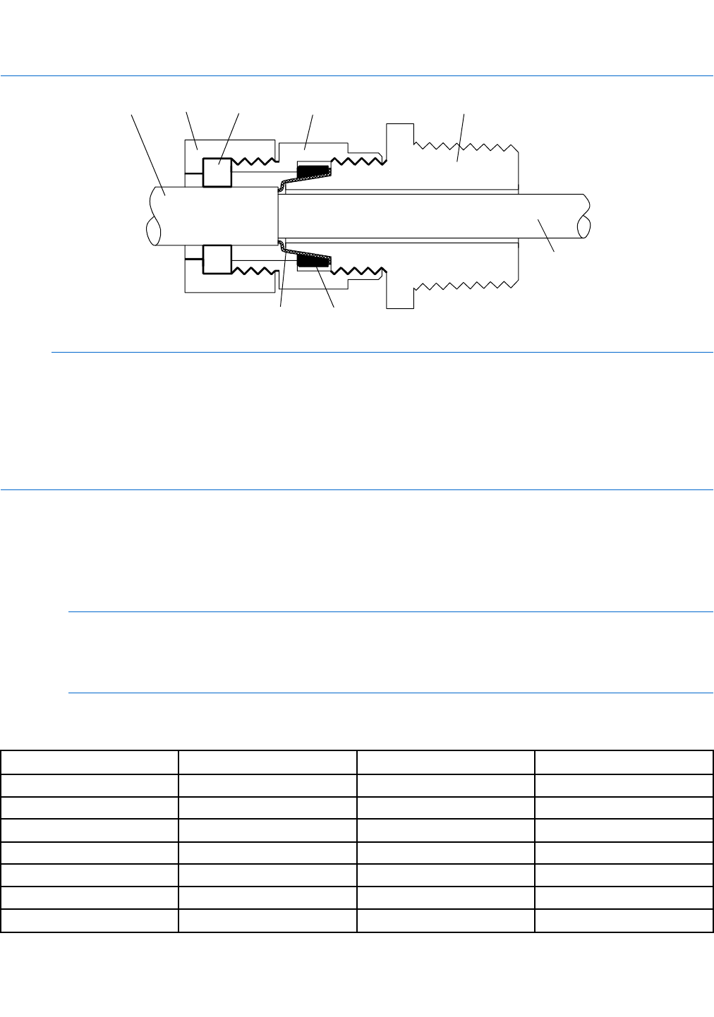
Figure 4-4 Cross-section of assembled cable gland with cable
A
B
C
D
E F
G
A
A Cable
B Sealing nut
C Seal
D Compression nut
E Braided shield
F Brass compression ring
G Nipple
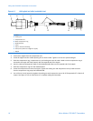
10. Remove the junction-box cover or transmitter housing cover.
11. At both the sensor and transmitter, connect the cable according to the following procedure:
a. Insert the stripped end of each wire into the corresponding terminal at the sensor and transmitter ends, matching
by color (see Table 4-3). No bare wires should remain exposed.
Note
For ELITE
®
, H-Series, T-Series, and some F-Series sensors, match the wire to the terminal by the color identied
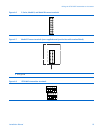
on the inside of the sensor junction box cover. See Sensor and transmitter terminals for illustrations identifying
the various sensor and 9739 MVD transmitter terminals.
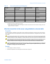
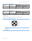
Table 4-3 Sensor and transmitter terminal designations
Wire color Sensor terminal Transmitter terminal
Function
Black
No connection
0
Drain wires
Brown
1 1
Drive +
Red
2 2
Drive −
Orange 3 3
Temperature −
Yellow
4 4
Temperature return
Green
5 5
Left pickoff +
Blue
6 6
Right pickoff +
InstallationManual17


