Wiringtheoutputs
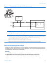
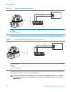
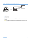
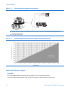
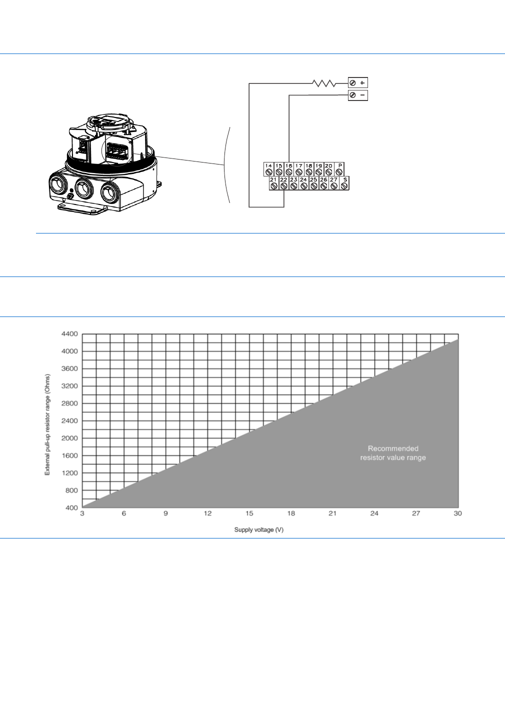
Figure 5-10 Wiring the discrete output for external power
A
B
A A pull-up resistor, which must be of sufcient value to limit loop current to less than 500 mA depending on total loop
resistance at the transmitter
B 3 to 30 VDC power supply
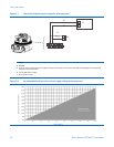
Figure 5-11 Recommended pull-up resistor versus supply voltage (external power)
Wire the discrete input
Procedure
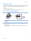
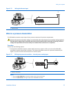
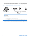
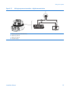
Use terminals 21 and 16 for the discrete input. See Figure 5-12 for wiring the discrete input.
The discrete input, frequency/pulse output, and discrete output share terminal 16 as a common return.
32MicroMotion9739MVDTransmitters


