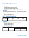
Wiringtheoutputs
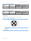
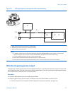
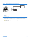
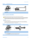
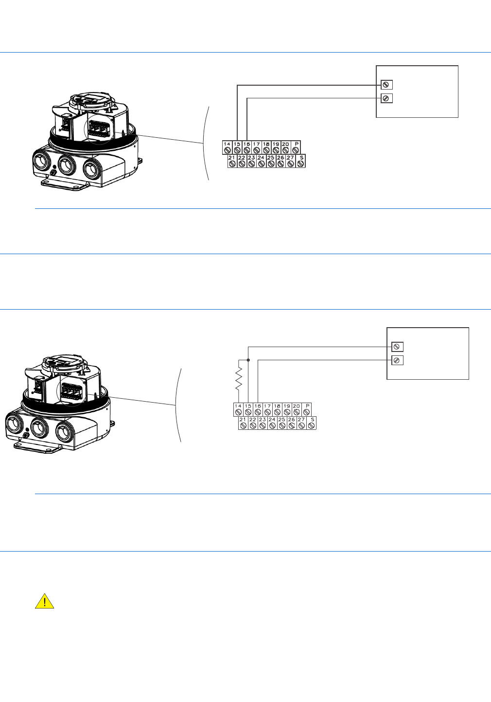
Figure 5-4 Wiring the frequency/pulse output
A
B
C
A FREQ+
B RETURN
C PLC or pulse counter
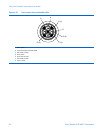
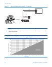
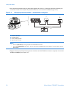
• To congure the output for increased current, add a 1 to 3 kΩ resistor across terminals 14 and 15 (see Figure 5-5).
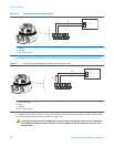
Figure 5-5 Wiring the frequency/pulse output for increased current
B
C
D
A
A 1 to 3 kΩ resistor
B FREQ+
C RETURN
D PLC or pulse counter
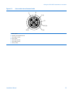
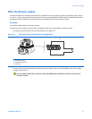
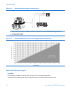
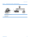
• To congure the output for constant current, add a jumper across terminals 14 and 15, and a 100 to 250 Ω resistor
at the PLC or pulse-counter end of the cable (see Figure 5-6).
If the frequency/pulse output is congured for constant current, the discrete output circuit is inoperable.
To recongure the discrete output to function, you can congure the discrete output for operation using
external power.
28MicroMotion9739MVDTransmitters


