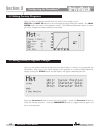
Detailed Parameters
®
32
Section 4
DriveRack
™
DriveRack™ User Manual
Section 4
The DriveRack™ units (480, 481 and 482) offer complete editing flexibility, by offering in-depth
control over every parameter within each effect module. The following section will provide
you with descriptions and explanations of all parameters within the DriveRack™ units.
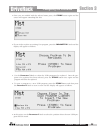
The signal routing begins at the INPUT ROUTING block of the DriveRack™ units. The input
may be configured as a signal router or a mixer. Please see section 3.5A for more information.
These parameters are user adjustable on all programs. Please see section A.9 of the Appendix
section for a complete input signal routing diagram.
Level -Inf to 20dB (Router Module)
Adjusts the input level of the selected input.
Input (Mixer module)
This parameter is used to select the input channel
Level Inf to 20dB (Mixer module)
This parameter is used to adjust the level for the selected channel.
Master level Inf to 20dB (Mixer module)
This parameter is used to control the overall output level of the mixed input signals.
High Pass Off, 15 - 118Hz (Mixer and Router)
Turns the High Pass filter on and off and selects the desired frequnecy from 15 to 118 Hz in
1/12 octave steps.
Pink Noise On/Off (Mixer and Router)
Turns the pink noise generator on and off.
Noise Level -10 to 10 (Mixer and Router)
Adjusts the overall level of the pink noise generator.
The 480, 481 and 482 DriveRack™ EQ sections may be configured as a single 31 band, dual
31 Show/House, 9 band parametric or a real time analyzer (ch. 3 and 4). For more informa-
tion on these configuration options, please see section 3.5B.
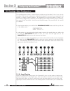
4.2.1 - 31 BAND GRAPHIC EQ (G)
EQ On/Off
Turns the GEQ on and off.
Flat Set/Undo
This parameter either flattens the GEQ or restores the GEQ to its original shape.
Frequency 20Hz to 20kHz
This parameter allows you to select any one the 31 available frequencies.
Level -12 to +12 dB
4.2 Pre-Crossover (EQ)
4.1 Input Routing (IN)


