Crestron C2N-DAP8RC Digital Audio Processor with Room Control
Operations Guide – DOC. 8187A Digital Audio Processor with Room Control: C2N-DAP8RC • 53
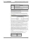
Built-in RS-232 Symbol Output Descriptions
OUTPUT(S) FUNCTION(S)
[rx$] More advanced signal processing can be done through serial strings and
the rx$ output line on the symbol.
[cts] CTS is an input to the program that monitors the “Clear to Send” line status
of the C2N-DAP8RC RS-232 port.
str2 The C2N-DAP8RC RS-232 port is capable of sending complex serial data in
the form of serial data strings on this output line.
NOTE: When present, the delimiter is appended to every string of text in the port
definition (both transmitted and received strings).
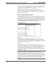
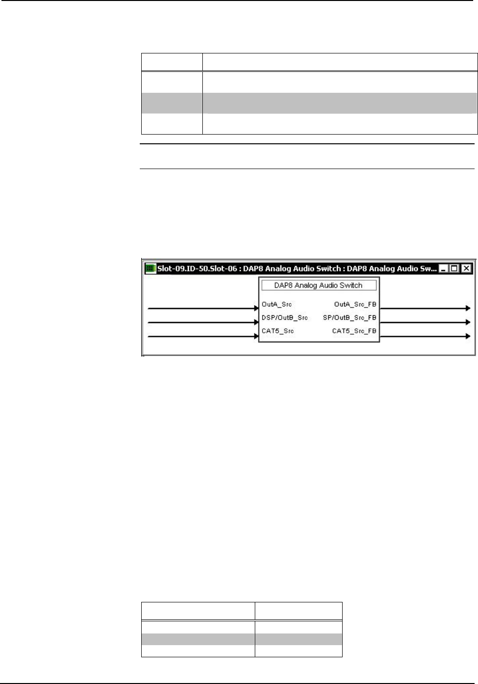
Slot 06: DAP8 Analog Audio Switch
The DAP8 Analog Audio Crosspoint is a 6x3 stereo analog audio crosspoint built
into slot 06 of the C2N-DAP8RC surround sound processor. The DAP8 Analog
Audio Crosspoint allows each of three stereo outputs to independently select one of
six stereo audio inputs.
The C2N-DAP8RC provides one CAT5 connector, labeled AUDIO, for stereo audio
input and output. That is, one twisted pair carries stereo audio to the unit, and the
other twisted pair carries stereo audio from the unit. The remaining audio inputs are
RCA left/right connectors, labeled AUDIO IN 2 through 6.
In addition to the CAT5 audio output, the C2N-DAP8RCprovides two left/right RCA
outputs, labeled A and B. Output A flows directly from the crosspoint with no
additional processing. Output B is passed through a volume/tone controller on slot 07
of the C2N-DAP8RC. Thus output B can be adjusted for volume, bass, and treble.
Refer to “Slot 07: Audio Output B Controls” on page 54.
Analog audio that is sent to output B will also be sent to the C2N-DAP8RC's internal
DSP (digital signal processor) if analog source is selected. The DSP settings are
controlled by the Surround Sound Decoder on slot 08; in some cases, the
programming of the Surround Sound Decoder may affect the Analog Audio Switch
settings. For example, if the program selects a different analog audio source for the
DSP, then that source will also be sent to output B (and the feedback will be updated
accordingly).
To switch a source to an output, each <Src> analog is initialized to a value that
corresponds to the source, as shown in the following table.
Analog Audio Symbol Source Signal Description (in Decimal Format)
AUDIO SOURCE VALUE
CAT5 1d
RCA 2d – 6d
No Source 0d


