


Digital Audio Processor with Room Control Crestron C2N-DAP8RC
8 • Digital Audio Processor with Room Control: C2N-DAP8RC Operations Guide - DOC. 8187A
For information on audio and video wiring, refer to “Hardware Hookup” which
begins on page 16.
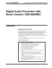
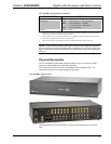
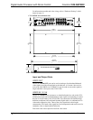
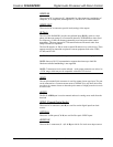
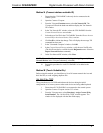
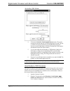
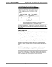
C2N DAP8RC Overall Dimensions
8.25 in
(20.95 cm)
3.31 in
(8.41 cm)
3.48 in
(8.84 cm)
3.47 in
(8.81 cm)
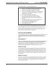
19.00 in
(48.26 cm)
17.10 in
(43.43 cm)
8.44 in
(21.44 cm)
16.91 in
(42.95 cm)
CRESTRON
ASU 74670 .J.N ,HGIELKCOR .CNI SCINORTCELE NORTSERC
ROSSECORP DNUOS DNUORRUS OIDUA LATIGID LANOISSEFORP
IR
SENS
DCB
IN
A
IR OUT
KIG
LJH
ECA
FDB
VIDEO OUT
VIDEO IN
1-2-3-4
VIDEO
OUT
1513
VIDEO IN
11
161412
75
86
9
10
321
VIDEO INPUT COMP
11 101 10 10
AUDIO
SETUP
RS-232
Y24 GZ
NET
B
C
A
SPDIF
D
R
L
2 3
OPTICAL
4
AUDIO IN
5 6
R
R
A
L
L
B
SURROUND SOUND OUT
SURROUND
AUDIO OUT
BACK CENTER
SUBWOOFER
FRONT
PWR
NET
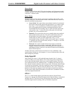
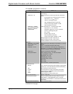
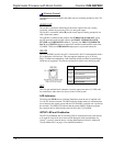
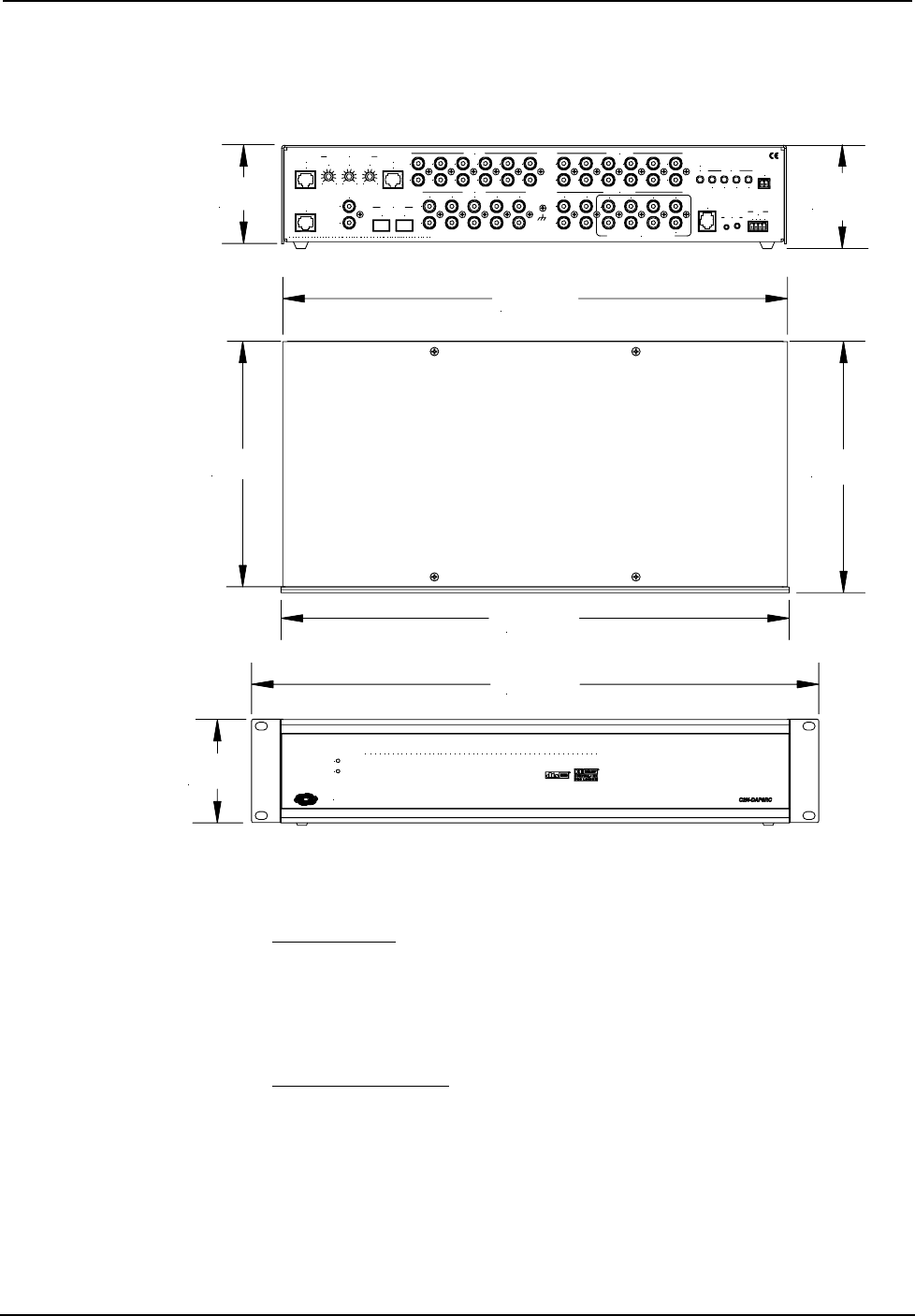
Input and Output Ports
VIDEO OUT
The RJ-45 VIDEO OUT port can be used to send up to four baseband/balanced
video signals out of the unit and back to the head end. A Crestron video receiver
such as the CNX-PBVR4 or CNXRMCLV must be used to convert the signals to
single-ended RCA for input to the CNX-PVID8.
VIDEO IN 1-2-3-4
The RJ-45 VIDEO IN port connects to a video distribution box such as the CNX-
PVID8 and accepts four baseband/balanced video signals corresponding to each of
the four levels provided by the CNX-PVID8. This connection can distribute high
definition component video and multi-channel digital audio, or combinations of S-
video and/or composite video. Three of the video signals have cable length
compensation. The fourth video signal has fixed compensation and can be used for
composite video or digital audio distribution.
Each local video source input has a built-in video sensor.