Digital Audio Processor with Room Control Crestron C2N-DAP8RC
50 • Digital Audio Processor with Room Control: C2N-DAP8RC Operations Guide - DOC. 8187A
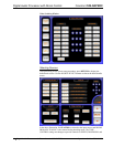
IR Device Symbol
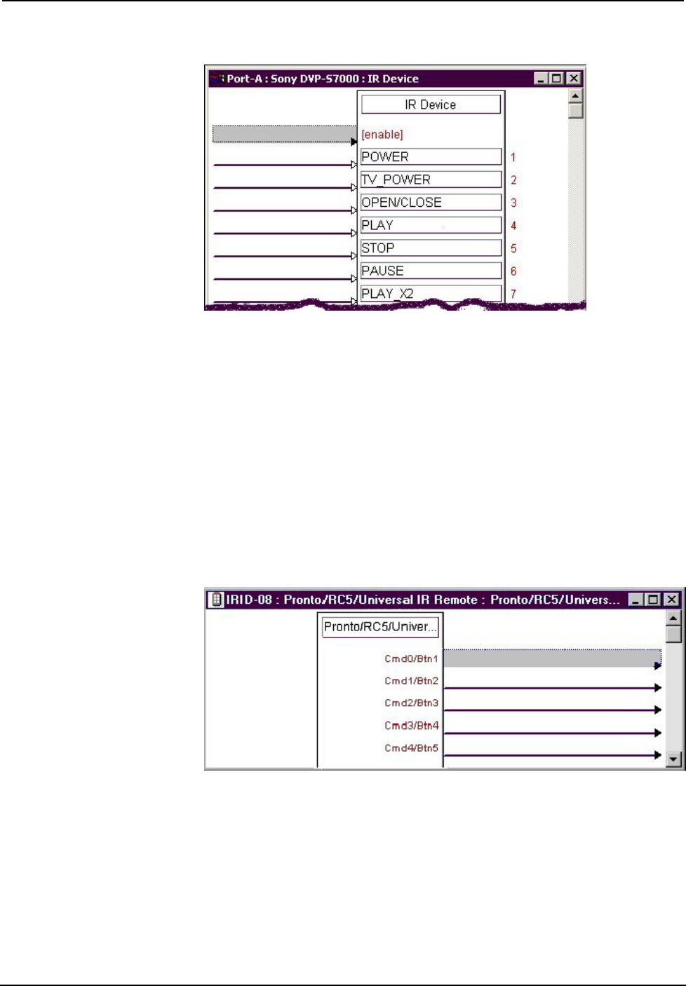
Slot 02: IR Receiver
This symbol is only used in systems containing an acceptable third party transmitter
(Pronto/RC5/Universal IR Remote). To include a compatible third party transmitter
as part of the program, you must first drop a wireless receiver (CNXRMIRD) from
the Wireless Receivers | Wireless Receivers (IR) folder of the Device Library into
slot 2. Then, from the Wireless Remotes (IR) folder, drop the Pronto/RC5/Universal
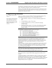
IR Remote symbol onto the CNXMIRD. The symbol, shown below, consists of a
number of outputs (presses), which correspond to the actual buttons on the
transmitter. Recall that when mapping the buttons on the third party transmitter, a list
was developed (refer to "Map the Universal Remote" on page 25 for the actual
procedure). That list needs to be transcribed to this symbol. Match the button ID
numbers from the list to the numbered press. These outputs are the driving source for
the IR devices.
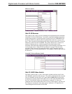
Pronto/RC5/Universal Remote Symbol
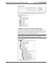
Slot 03: DAP8 Video Switch
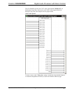
The DAP8 Video Switch is a 16x16 video matrix switcher built into slot 03 of the
C2N-DAP8RC surround sound processor. The symbol is illustrated on the next page.
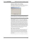
The C2N-DAP8RC provides one CAT5 input, labeled VIDEO IN 1-2-3-4 (where
twisted pair #4 can carry digital audio) and 12 RCA video inputs labeled 5 through
16. The C2N-DAP8RC accepts any combination of composite, S-video, and
component video, and switches these sources to up to sixteen outputs. Typically, the
RCA inputs are connected to local video sources, while the CAT5 input receives
video and digital audio from the CNX-PVID8.


