


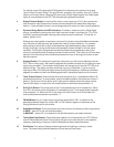
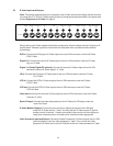

Video) to the appropriate “dig.2 in” jack.
Digital 2 in: This input is recommended for an audio/video source (DSS receiver, etc.) with a
TOSlink (optical) digital output.
Remember that the composite video connection will go to the yellow-center RCA jack
immediately under the “dig.2 in” label.
Connect the source’s TOSlink (optical) digital output to the GTP-760’s TOSlink socket located
under the “dig.2 in” label.
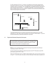
Digital 1 in (RF): We recommend this input for laserdisc players with a digital RF output.
It is the only input on the GTP-760 equipped with the RF demodulator needed to process a
laserdisc’s Dolby Digital encoded soundtrack.
Connections follow the same pattern detailed in “DVD in” and “Dig.2 in” above. Connect the
laserdisc player’s composite video output to the yellow-center RCA jack immediately under the
“dig.1” label. Then connect the player’s coaxial digital output to the black-center RCA jack
under the “dig.1 in” label.
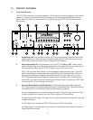
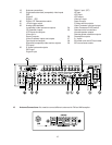
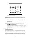
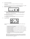
20 Digital 1 RF Demodulator (bypass) Switch
(see illustration on preceding page)
This switch adds flexibility to the GTP-760. If you play laserdiscs with Dolby Digital-encoded
soundtracks, put this switch in the IN position. This places the demodulator circuit in the signal
path and allows proper Dolby Digital decoding.
If you do not have a laserdisc player with a digital RF output, place the switch in the OUT
position. You can then use this input in exactly the same way as you would use the DVD input.
DVD
in in in
digital 2 digital 1
DVD
in in in
in out
digital 2 digital 1
dig1RF
demodulator
Standard
video
in
LD
12V
trigger out
L
R
in
12