


22
MECHANI CAL INSTALLATION 110CS
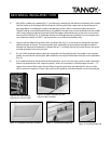
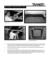
5) Install t he 4 supplied 3 / 4 ” wood scre w s being care ful not t o strip the hole s in the su bwoofe r.
Two additional anchor screws should be installedup near the toprear edge of the subwoofer in the cavity
w he re the con trol panel is locat e d. The posit ion of t he se t wo screws should correspond to the v ertical pencil
lines dr awn earlier.
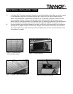
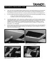
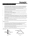
6) Drill a hole in the cabinet a t e a ch pencil line, 1” from the t op edge of t he cabinet and in sta ll an appr opriate la g
screw* t hrough e a ch and into th e wall st uds.
PLEASE N OTE th at there will b e a space between the wall and the cabinet.
These two screws shouldbe firm, but do not attempt to over tighten or close the cabinet/wall gap by force of
t he screw. The scre ws are for pre vent ing t he su bwoofe r from falling for wa rd and do not su pport the w e ight of
the unit. (Fig. 3)
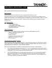
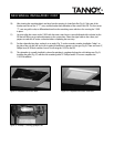
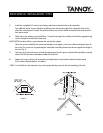
7) On ce th e u n it is level an d secure , reinstall th e b o t to m p an el an d its sp acers with t he A llen h ead b o lts rem o ved
earlier . Peel o ff an d rem o ve th e b o t to m ru b b er feet if d esired .
8) Replace the snap-on lid once all con nections and adjustments to the interface panel h ave b een made.
(See “In terface M o d ule Op tio n s” fo r d etails.)
* NOTE: As wall th ickne ss a nd materia ls v a ry, we do not provide lag scre ws for the wa ll mount ing of t he rails.
Fig ure 3
Fig ure 4