


19
MECHANI CAL INS TALLATION 110SR
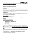
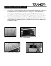
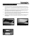
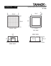
10 ) After clearing t he remaining de bris and dust from t he opening, it should look like (Fig . 6 ) . Ta ke not e of th e
location and color of the 11 “ T” - nuts, and the location and orientation of the cutout in the PIR. The four corner
“T ”-n ut s are gold in co lo r , to d ifferen tiate th em fro m t h e remain in g se ven w hich are fo r securin g t h e 110SR
in place .
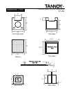
11) Yo u mu st alig n t h e cut o u t o n th e 110SR with t h e same co n tro l access cu to u t (in d icat ed w ith red p ain t) o n th e
PI R that will allow y ou t o make adjust me nt s t o t he system later. Orient the signa l cable to t he cu tout, a nd
prepare to make the AC mains connection before completing the next step.
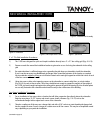
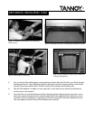
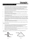
12 ) Put the subwoofer into place , resting it on an a ngl e (Fig . 7) on t he seconda ry w ooden inst allation “ledge” on
the side of the s ub; this will ass ist you in getting a hand free to operate a screw gun (Fig. 8). There are seven 3” ,
Phillips-h ea d, 8 -32 black machine screw s for securin g the 11 0 SR t o t he PIR.
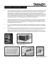
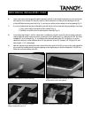
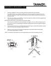
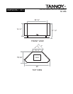
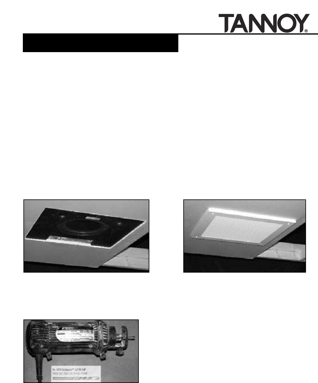
13 ) T he subw oofe r is normally insta lle d in place after paint ing is comple ted t o ke e p t he su b looking new (Fig . 9 ) .
Insta lling the grille (Fig . 1 0 ) w ith the four re maining w hit e 3 ” Phillips-he ad 8-32 screws completes t he
11 0 SR inst alla ti on.
Figure 9: Completed subwoofer detail. Figure 10: Completed subwoofer installation.
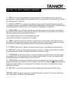
Figure 11: Rotozip™ showing guidepoint bit.