


21
MECHANI CAL INS TALLATION 110CS
1) At y our de sire d locat ion, esta blish a “bot tom” mark in t he corner. For a minimum re commended spa ce of 6 ”
bet w e en t he t op of th e su bwoofe r and t he ce iling (t o access t he conn e ct or panel), t his mark shou ld fall a t le ast
2 0 ” fr om the cei li ng. Extend a 2 0 ” level, h oriz onta l pencil line on e a ch side of the corn er. Do not inst all the
subwoofer t oo close to th e ce iling so a s not to a llow for conne ct ion or adjustment , if required.
2) Using a stud sensor, locat e the e nd most st uds w ith in the 20 ” h orizont a l line s. Ma rk ea ch and e x tend a plumb
vertical pencil line from thes e points up the wall for 20” .
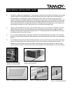
3) Align th e right bracke t atop t he right 20 ” horizont al line with the flange on t he bott om and t he 45 degree cut
end tight to the corner . Check for level.
4) At tach the ra il secur e ly to a st ud w ith an a ppropriat e lag scre w * t hrou gh hole “D”. Be sure the he ad of th e
screw does not protrude more than 3/16” . (Figs . 1 & 2)
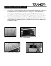
5) Po sitio n th e left rail with its 45 d e gree cu t en d tig ht to th e co rner, level an d eve n wit h th e rig h t rail an d secure
to a stud through ho le “D”. (Fig. 2)
6) There are three holes at the far most end of the rails fromthe corner; “A”,“B” and “C”. Hole “B” corresponds to
a point 16” from hole “ D” and should conform to a standard s tud pos ition. Holes “A” and “ C” are 3/4” on each
side of hole “B” a nd allow for variance s of st ud locat ion. Sh ould you encount er a stud locat ion ina cce ssible by
w ay o f an y o f th ese holes, yo u ’ll n eed to d rill new mo u nt in g h o les in th e b rackets co rresp o n d ing t o yo u r vertical
pencil lines . (Fig. 2)
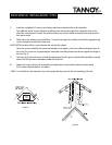
7) On ce yo u’ve aligned one of the holes to a stud, check fo r level and securely fasten the rail to the stud with a
suitable lag screw*. Repe at t his proce dure f or th e othe r rail.
8) The rails sh ould be level w it h e ach ot her and secur e ly fa st e ned. The y must be capable of su pport ing a 4 5 lb load.
S UB WOOFER I NS TALLATI ON:
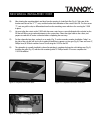
1) Remo v e t h e t o p fro m y o u r 110CS by p u lling firmly upw a rd at th e out e r edges of t he lid and se t t he lid a side .
2) Lay t he cabin e t face (log o side ) do wn o n a soft su rface an d remov e t he bot t om plat e an d space rs by
unscrewing the 4 Allen head pan bolts on the bottom of the sub. Set these parts as ide.
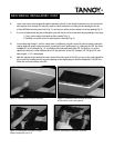
3) Two people should now lift t he su b (w ith the driv er side facin g down) and pla ce it atop t he t w o inst alle d rails.
Push the unit a ll the w a y int o the corner and hold in pla ce.
4) While on e pe rson holds the su bw oofe r, the second person shou ld dr ill pilot holes for t he 3/4 ” screw s t hrou gh
rail h oles “E” and “F” and into the sub w oofer cabinet . ( Fig . 2 )
F
E
A
B
C
D
Figure 1 Figure 2
* NOTE: As wall thickne ss a nd materia ls v ary, w e do not provide lag scre ws for the wa ll mou nt ing of t he rails.
(co n t inu e d o n p ag e 14)