


13
MECHANI CAL INS TALLATION 110TB
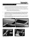
2’ x 2’ Tile Grid Installation Proced ures:
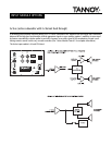
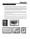
1) The 11 0 T B w as designed for quick and simple in sta llati on dire ctly in to a 2 ’ x 2’ T-bar ce iling g rid (Figs. 9 & 1 0 ).
2) Re mov e sev e ra l tiles arou nd t he insta llat ion locat ion t o g ain easie r acce ss for lacing t he su bwoofer in the ce iling
grid .
3) Be certain that there is sufficient hanger wire suspending the grid where you intended to install the subwoofer.
If n ot , it may be ne cessary t o add add itional grid h anger w ire s a roun d t he perimet e r of t he locat ion , as required.
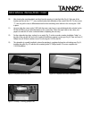
We recomme nd a min imum
of four pe r su b locatio n located o n t he main gr id support bar w ith in fo ur in che s of e ach
of the four corners of the subwoofer.
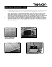
4) Using wir e rope or chain, se le ct opposin g corners on t he su bwoof e r to connect safe t y line s, or seismic teth e rs
(Figs. 8 & 9) s ecurely to the structure. These lines should be taut enough to support the majority of the weight of
th e 110TB, y et leave en ou gh lo ad ag ain st th e ceilin g grid to pre v e nt t he grid from bu z zing. Be sure all t eth e r points
are securely fasten ed to th e su b wo o fer and ach o red secu rely to th e sub st ructu re o f th e b u ild in g .
Fr
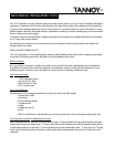
ee Space Installation Procedures
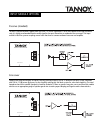
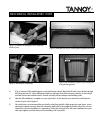
1) For an in st a llat ion in fre e space, se lect a locat ion that will allow su spe nsion from dire ct ly abov e t he su bwoof e r.
Beg in b y m easu ring a 19-1/2” sq u are, and at each co rn er , install a fasten er (Fig . 11 & 12) su ch as t he
recommended hanger bolt to support each corner of the subwoofer.
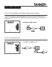
2) Thread a coupling nut all the way over a hanger bolt, and with a 9/16” s ocket s et, start threading the hanger bolt
int o t he su pport stru ct ure. Secure a h a nge r t o a substruct ure at all four corn e rs. This ma y be acco mplish e d se ver al
ways depending on your particular installation.
(continued on page 14)
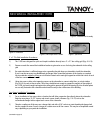
Figure 1: Hanger Bolt
Figure 2: Coupling Nut
Fig ure 3: Backing N ut
Figure 4: Threaded Rod Assembly
Figure 5: Turnbuck le
Figure 6: Wire Rope Nut & Thimble
Figure 7: Quick-link