


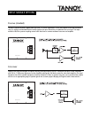


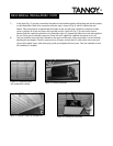

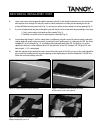


3) Back o ff the coupling nut com pletely (Fig. 11) and thread o n a backing nut with which to lock threads to the coupler .
Hold the coupler up to the hanger bolt to estimate the half way point of the coupler, and set the backing nut to
that height before re- installing the coupler and tightening it in place with a socket and an open end wrench.
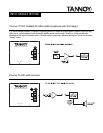
Thread a backing nut onto the threaded rod (or an eyebolt) far enough s o the rod can be threaded into the coupler
un til it sto p s, h aving reach ed th e h ang er b o lt in sid e . N o w tig h ten u p th e b ackin g n ut o n th e ro d to secure it fro m
t urn ing, until it looks like (F ig . 4 ). Reme mbe r t hat t he rod cou ld othe rw ise be an eyebolt , if y ou are usin g t he w ire
rope suspensionmethod, or a Hilti™ type fastener. Be sure to follow local building codes.
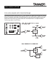
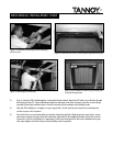
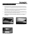
4) Alw ay s install and u t iliz e all fou r point s, and it shou ld look like (F ig . 1 3 ). In t his phot o, t he t urn buckles h a v e be e n
added to the ends of the rods. The closed eyebo lt on the turnb uckle has been remo ved and replaced with the
threaded rod. N ote that the turnb uckle is stamp ed with an “ L ” to identify the load or live end. Ob serve the correct
ass embly procedure from rod to eye- hook.
5) It’s now a fairly simple proce dur e to place t he su bwoof er on to t he aw a it ing h ooks. Two people, on t w o separate
ladders can n ow h oist t he sub in t o place . Wh e n in st alle d , it can ea sily be le v e led w it h a few t u rns o n t h e turn bu ckle s
(Fig . 14).
6) If no su ita ble point e x ist s dir e ct ly above t he desir e d locat ion , y ou can u se w ire ro pe or ch a in t o make conn e ct ions
that are not perpendicular to the suspensionpoint(s). Under nocircumstances shouldthe angles exceed +/- 15
degrees from vertical. Make certain that you follo w closely the instructions and regulations for the use of wire
rope for overhead suspension. Serious injury could result if guidelines and safety margins are not closely obeyed.
14
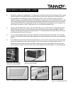
MECHANI CAL INS TALLATION 110TB
Figure 8: Wire rope detailing
suspension or seismic tether
Figure 9: Installed subwoofer top view,
only two c hains attached
Figure 10: Completed subwoofer installation.
Figure 11: Installing the hanger bolt
Figure 12: Installed hanger bolt