


16
MECHANI CAL INS TALLATION 110SR
NEW / EXISTING CONSTRUCTION INST ALLATION PROCEDURES:
Before
You Begin:
Please read an d u n derstand all o f th ese in structio ns t h o ro u gh ly b efo re b eg in n in g an y w o rk.
Note that all construction work for the installation of all Tannoy products must be done to local building codes by
qualified, licensed insta llers. A loca l building inspector should approve any ove rhea d installations. Always use safety
goggles when cutting material using a Rotozip™ . Tannoy as sumes no liability for caus e and effect of improper
insta llation work.
Y
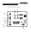
our Package Includes:
• 110 SR su b w o o fer sy stem
• 1 1 piece supplied scre w package
• Pre-Insta llation ring ( P IR - SOLD SEPARAT ELY)
• Indiv idua lly packaged grille
T
ools/ Parts Required:
Th e fo llo w in g is a list o f su g g est ed m aterials and to o ls. You r need s m ay d iffer slig ht ly at each site:
• Rotozip™ cutout tool and Guidepoint™ bit
•2-1/2”#8woodscrews
• Co rdless screw g u n
• Combination s quare and /or tape measure
• Additiona l 2” x 4 ” lumber, in 2 4 ” piece s
• Trim saw (opt ional)
Site
Preparatio n and Installation Proced ures:
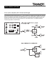
Please n o te th at th e 110SR is d esig n ed fo r in st allatio n in a ceilin g with exp o se d ceilin g jo ists. T he PIR m u st b e secu red
t o t he su pport st ruct ure ; dry wall alone w ill n ot su pport the w e ight of the subw oofe r. Make certa in t hat the re is sufficie nt
clearanceabovethejoist(minimum12”)forthesubwooferinstallation.
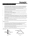
Please refer to the photographs as a guideline for installing the PIR into a wood joist or steel s tud ceiling.
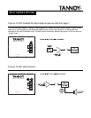
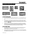
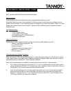
1) (Fig. 1) M easu re t h e lo catio n s fo r t wo 24” st rip s of 2” x 2” or 2” x 4” blo ckin g. These m u st b e used in o rd er fo r
secu re mo unting to the PIR with 2-1/2” #8 wood screws. Use a com bination square to m easure the thickness of
the PIR (app rox. 5/8” ), and then transfer the m easurement to the jo ist.
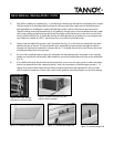
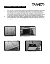
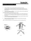
2) (F ig . 2 ) Screw th e blocking t o the joist w ith se ver al evenly spaced scre ws. ( Fig. 3) Fast e n t he PIR similarly t o
t he blockin g. Note t hat t he re are no pre-drilled holes; use t he wood screws t o go direct ly th rough the PI R,
ke e ping a 1” c le arance from any “T”-n ut s. Not e : the PIR mu st be inst alle d w ith “T”-nut s on the top side. T he
PI R is cle arly ma rke d for your safe ty and con venience.