


20
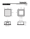
MECHANI CAL INS TALLATION 110CS
Th e 110CS su b w o o fer is easily installed in alm o st an y in d o o r lo cat io n w h ere access to a co rn er is av ailab le . A lt h o u gh its
appearance is handsome in full view, the wide dis persion of its down firing woofer and the dis persion of low frequencies
in gene ral, a llow mode rate obstruct ions such as cha irs, plant s etc. t o be pla ced di re ctly in front of the cabinet. A corne r
posit ion aga inst solid wa lls will height e n t he bass pe rformance re sult ing in a woof e r soundin g larger and more pow e rful
than its compact size would suggest.
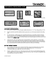
In locations where the situation dictates a higher positioning of the subwoofer, the s upplied wall brackets for mounting
to 16” cen ter st u d s m ay be u tilized .
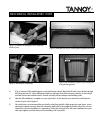
All connections and controls are access ed under the snap- on top panel. Note the hole provided in the cabinet rear
t hrough w hich to run cable s.
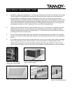
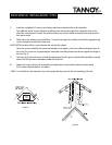
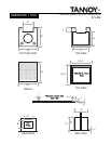
I NS TAL LATI ON OF COR NE R R AI L K I T
Th e 110CS su b w o o fer is a free standin g d esig n . H owev er , with in stallatio n o f th e co rn er rail kit, m o u n ting at any h eig h t
is possibl e. The follow ing in struct ions will guide you in t he in sta llati on of t he rail kit .
Before
You Begin:
Be sure to follow instructions carefully and conform t o an y and all local codes regarding this type of insta lla tion.
A qualified, license d installer should be retained for any behind t he wall pre-wiring w ith final approval of a local
building inspect or. Tannoy a ssumes no liability for cause and e ffect of improper installation work.
Y
our Package Includes:
• 110C S su b w o o fer system
• Le ft side r ail, 2 0 ” long
• Right side ra il, 2 0 ” long
•(4)
3/4” wood screws
T
ools/ Parts Required:
The follow ing is a list of sugge sted mat eria ls and t ools. Your nee ds may differ slig htly.
•Framinglevelw/rule
•Studsensor
• Ele ct ric drill and drill bit s
• Screwd river b its
•Ladder
•Suitablelagscrews*
•Pencil
* NOTE: As wall thickness and mat eria ls v ary, w e do not prov ide lag screws for the wall moun ting of t he rails.
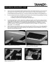
Site
Preparatio n and Rail Kit Mounting Instructions:
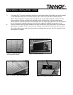
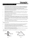
New construction and m ost retro fits sho uld includ e two single “ J” Boxes installed in the drywall with p ower and signal
cables w ithin. Position the height of the “J” Boxes so t hat th ey will be hidde n by t he installed subw oofe r cabinet and at
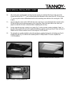
a vertical p lacement o f n o more than 7” from the d rywall co rner to the o utside edg e of the “ J” Box (see Fig. 4). The g ap
in t he corner be hind t he insta lle d subw oofe r a nd t he dry wall will prov ide adequat e cle arance for all cable runs t o t he
subwoofer.