


10
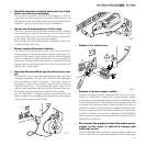
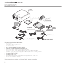
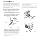
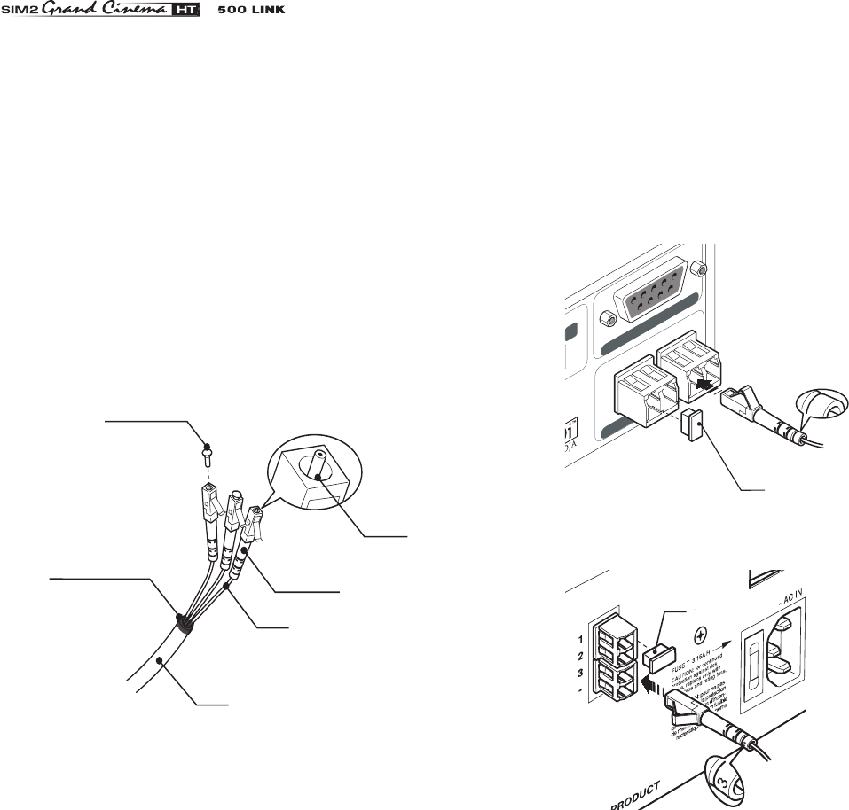
Protective cap
Separation point
Cable
Fibre
Connector
Ferrule
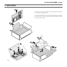
CONNECTING THE TWO UNITS
The system can be fully controlled using the supplied IR (infra
-
red) remote control handset. There is a single remote control
for both the DigiOptic™ Image Processor and the Projector; the
remote control can be directed towards either unit since they
are both equipped with an IR sensor.
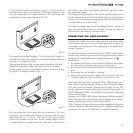
The connection between the two units is made with a single
cable containing three fibre optic cables each terminating in
an LC connector. The standard cable length of 20m will be
sufficient for most installation requirements.
During installation of the fibre optic cable:
• The individual optical cables are delicate: always handle
the main cable without touching the individual optical ca-
bles (Fig. 7).
Never pull the individual optical cables or connectors; if
necessary, you may pull the main three-core cable.
• Check that the connectors are correctly inserted.
• Make sure that the cable does not constitute an obstacle
for persons moving around the room.
• Take care not to create knots in the cable; the minimum
radius of bends in the cable is 2 cm.
• Prevent the cable from pulling and mechanical stress: this
could cause the connectors to be pulled out and dama-
ged.
Fig.7
Fig.8
Fig.9
• Only remove the cap protecting the connector ferrule im-
mediately before inserting the connector; if the ferrule is
allowed to come into contact with foreign material it may
be damaged, making the connector unusable.
• Take particular care when inserting fibre optic connectors in
their respective sockets on the rear panel of the DigiOptic™
Image Processor and the rear panel of the Projector.
• Make sure that the single optical cables are not switched:
the numbers on the cables must match the numbers on
the connectors (Fig.8-9).
CONTROL (RS 232)
OPTICAL FIBER LINK
3 -
1
2
12
3
3
Protective
cap
Protective
cap