


9
4 INSTALLATION
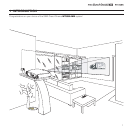
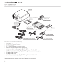
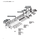
POSITIONING THE TWO UNITS
The HT500LINK system consists of two separate units (the DigiOptic™ Image Processor and the Projector), each of which is
equipped with a power cable; the two units are interconnected by a 20 m fibre optic cable.
DIGIOP
TIC ™
IM
AG
E PR
OCE
SSO
R
OF
F
ON
Fig.6
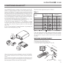
POSITIONING PROJECTOR
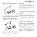
Position the projector on a stable, suitable platform or utilise
the optional bracket for a fixed ceiling installation.
CAUTION: In the case of ceiling mounting using a suspen-
sion bracket, follow the instructions carefully and comply with
the safety standards you will find in the box together with the
bracket. If you use a bracket different to the one supplied by
SIM2 Multimedia, you must make sure that the projector is at
least 65 mm (2-9/16 inch) from the ceiling and that the bracket
is not obstructing the air vents of the projector.
Position the projector the desired distance from the screen: the
size of the projected image is determined by the distance from
the lens of the projector to the screen and the zoom setting.
See
ADDITIONAL INFORMATION
for more information.
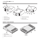
POSITIONING DIGIOPTIC™ IMAGE PROCESSOR
The ideal location for the DigiOptic™ Image Processor is on
a cabinet shelf or on a rack (dimensions compatible with a
standard 19" rack). Make sure that the support surface is stable
and that the unit has sufficient space around it for ventilation
purposes (at least 3 cm).
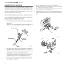
The unit is connected to the mains via an external power supply
unit with an output of +7 Vdc; the unit’s main power switch is
on the power supply unit.Connect the power supply unit output
cable to the
POWER
socket located on the rear panel (Fig. 2).
Use exclusively the power supply unit provided with the sy
-
stem or an alternative power supply unit expressly approved
by SIM2.
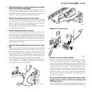
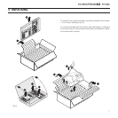
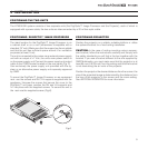
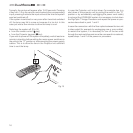
To mount the DigiOptic™ Image Processor on an equipment
rack use the screws and RH / LH supports supplied with the
appliance. Unscrew the screws that secure the cover to the
DigiOptic™ unit base, position the RH and LH supports and
fix into place with the supplied screws. To secure the unit to
the rack use the supplied screws
(Fig.6).