


ENGLISH
11
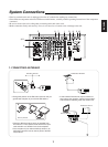
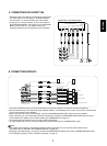
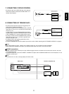
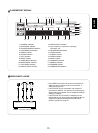
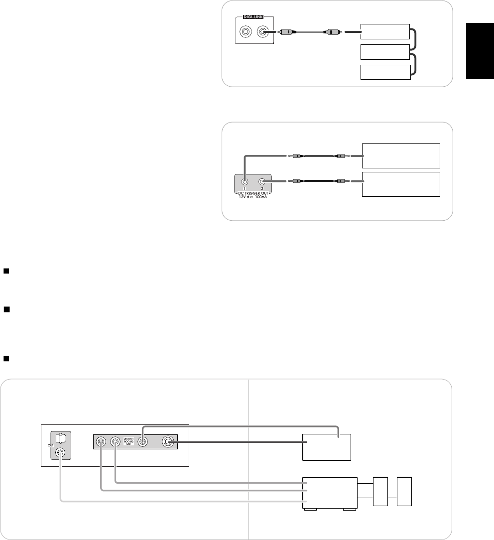
7. CONNECTING SYSTEM CONTROL
• Connect this jack to the DIGI LINK jack of the external
Sherwood component that uses the DIGI LINK II or III
remote control system.
8. CONNECTING DC TRIGGER OUTs
• Connect components that need to be triggered by DC
under certain conditions as follows :
• Connect a component to DC TRIGGER OUT 1 jack that
allows DC 12 V to turn on or off when this unit’s power is
turned on or off.
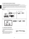
In case that this unit is connected to Sherwood power
amplifier A-965, connect DC TRIGGER IN jack of A-965
to DC TRIGGER OUT 1 jack for system power control.
• Connect a component to DC TRIGGER OUT 2 jack that
allows DC 12 V to turn on or off when a specific input
source is selected or not.
• For details, refer to the operating instructions of the
components to be connected .
• To link DC TRIGGER OUT 2 with a specific input source, refer to “When selecting the DC TRIGGER 2 SETUP” on page 55.
Notes :
• This output voltage (12 V d.c., 100mA ) is for (status) control only, it is not sufficient for drive capability.
• When making DC TRIGGER connection, you should use the stereo mini cord, not a mono mini cord.
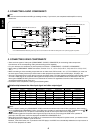
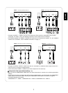
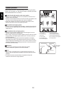
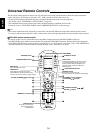
ROOM 2 connections
• ROOM 2 playback feature allows you to play a different program source in another room as well as one source in the main
room at the same time.
• For ROOM 2 playback, connect the VIDEO 2 / ROOM 2 OUT jacks and the COAXIAL DIGITAL OUT to the amplifier, TV. etc.
installed in another room.
Note :
• To minimize hum or noise, use high quality connection cords.
System
control
cord
Sherwood component
with DIGI LINK II or III
CD player
Tape deck
DVD player
Component to be triggered
by DC when this unit's power
is turned on
Component to be triggered
by DC when a specific input
source is selected
TV or projector
IN
S-VIDEO
IN
VIDEO
Amplifier
Another room(Room 2)Main room
This unit
Speakers
AUDIO
IN
R
L
COAXIAL
DIGITAL IN