


MULTI-ROOM SYSTEM CONTROLLER RMZ-955
8
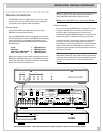
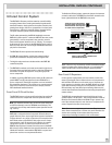
Installation: RMZ-955 Controller
This section covers all hardware installation and configuration
issues related to the RMZ-955 controller, including wiring con-
nections for AC power, source connections, speaker connec-
tions, pre-amp connections, data cable connections to the
remote zones, Infrared control connections, and special features
such as the paging feature. The next section of the manual (see
page 12) covers similar topics related to the installation, wiring,
and hardware configuration of the zone control devices – the
RSM-901 Sensor/Display and the RKP-901 Keypad.
For the sake of simplicity, these two sections cover the installa-
tion of a basic 4-zone system with a single RMZ-955 controller,
since this is the most typical system configuration. There is a
separate section
Installation: Multi-controller Systems
(page 15)
that covers installation, wiring, and configuration topics related
to larger, more complex systems with multiple RMZ-955 control-
lers.
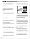
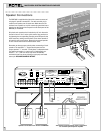
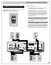
AC Line Connections
AC for the RMZ-955
Plug the RMZ-955 controller/amplifier into an unswitched AC
source only, i.e. a wall outlet. It is essential for proper system op-
eration that the RMZ-955 be plugged into a constant source of
AC power, since it has “stand-by” circuitry that must receive
power for full control from any zone at any time.
We recommend a powerline filter as the RMZ-955 contains a
number of microprocessor ICs that may benefit from the extra
protection afforded by a quality filter/surge protector.
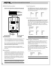
AC for Source Components
The RMZ-955 has two rear panel AC convenience outlets, one
switched and the other unswitched. These may be used to sup-
ply power for components used with the RMZ-955. Each outlet
carries a maximum load rating of 100 watts.
Unswitched AC outlet: The RMZ-955’s Unswitched AC outlet
supplies AC current whenever the RMZ-955 is plugged into a live
AC source. This outlet is NOT controlled by the setting of the
RMZ-955’s front panel power switch.
Switched AC outlet: This outlet provides a mechanism for con-
trolling AC power to other components, such as source compo-
nents. When the RMZ-955’s front panel switch is Off, the
switched AC outlet is also off. Even when the front panel switch
is turned On (i.e., when the RMZ-955 first powers up to
“Standby” mode), the switched outlet remains off until the
RMZ-955 receives a zone activation command from one of the
remote zones. The switched AC outlet then remains on until the
front panel power switch is turned Off or the RMZ-955 receives a
“system shutdown” command from a remote zone.
The switched outlet provides the mechanism for “powering up”
or “powering down” all of the source components from the re-
mote zones. We recommend plugging the AC power cords from
the source components into the switched outlet on the back of
the RMZ-955.
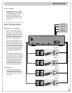
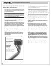
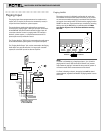
Rotel RLC-900 AC line conditioner/switcher
We strongly recommend the use of the RLC-900 AC line condi-
tioner/switcher to improve both the performance and convenient
operation of all system components. The RLC-900’s benefits in-
clude increased protection from AC power line surges and im-
proved system AC power management for proper turn-on and
turn-off sequences.
To incorporate the RLC-900, follow these steps:
a) Plug all system source components into the RLC-900’s “Digital
Equipment” or “Accessories” outlets as appropriate.
b) Plug the RMZ-955’s AC power cord into the RLC-900’s
“UNSWITCHED” outlet.
c) Plug the RLC-900’s “Control Cord” into the RMZ-955’s SWITCHED
outlet.
d) Plug the RLC-900’s “Main Power” cord into an unswitched AC
outlet such as a wall receptacle, etc.
When a system activation command is sent from a remote zone, the
RLC-900 turns on all source components automatically.
Special AC features
Some source components power up in a standby mode when AC
power from a switched outlet turns them on. These components
require a separate command to fully activate them. The RMZ-955
has a built-in software function, called “power toggle” that can
handle this “power up” sequence, if necessary. This feature is
fully described in the
System Set-up
& Programming
section of
this manual on page 22.