


MULTI-ROOM SYSTEM CONTROLLER RMZ-955
6
tions which allow linking additional RMZ-955 controllers for large
systems. Depending on the design of the associated compo-
nents, these pass-through source connections may alternatively
be used to “share” source components with a separate home
theater or audio system.
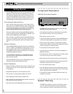
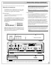
Placement
Place the RMZ-955 on a stable surface in an equipment rack or
cabinet. Note that the RMZ-955 is slightly deeper than most
source components (tuners, CD players, cassette decks, etc.)
and should not generally be placed on top of these units.
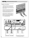
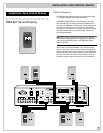
Connections:
Make sure that you have enough room to run all the connecting
cables and dress them appropriately behind the RMZ-955. Al-
though we’ll explain each connection fully in following sections
of this manual, glance through the following list of possible con-
nections and decide how much space you’ll need.
a) Four pair of RCA interconnects – one pair from each source.
b) Eight heavy gauge speaker cables (two for each zone).
c) Four six-conductor + shield data cables, each terminated with
the proper IDC strip connector.
d) One shielded RCA to RCA interconnect for RC-5 remote control
code connection.
e) One pair of RCA to RCA interconnects to power amplifiers from
each corresponding zone’s “Pre-out” terminals.
f) Up to four mini-plug (3.5 mm) cables from the RMZ-955’s “Infra
Red” outputs to remote IR transmitters.
g) Four more pair of RCA to RCA interconnect cables – one each to
the appropriate input of the next RMZ-955 in large multi-control-
ler systems.
h) Additional loudspeaker connections as required for systems us-
ing more than one RMZ-955 controller/amplifier.
i) 3.5 mm to 3.5 mm cable for AC “link” connections as required for
systems using more than one RMZ-955 controller/amplifier.
j) Up to six “TX-FORM” terminal block jumper wires needed when
cascading multiple RMZ-955 controller/amplifiers.
We STRONGLY RECOMMEND that you attach a tag or strip to
each cable and wire to identify it (e.g. “To Input 3 from tape
deck.”). This will help in troubleshooting as well as make future
service calls or system add-ons much less frustrating.
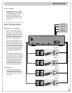
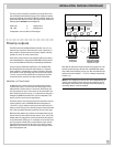
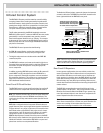
IR Flood Emitter
The RMZ-955 has a high intensity front panel IR flood emitter de-
signed to transmit commands from the remote zones to the ap-
propriate source component. Although exact performance will
vary, this high power transmitter has an effective operating
range of approximately 40' under normal conditions.
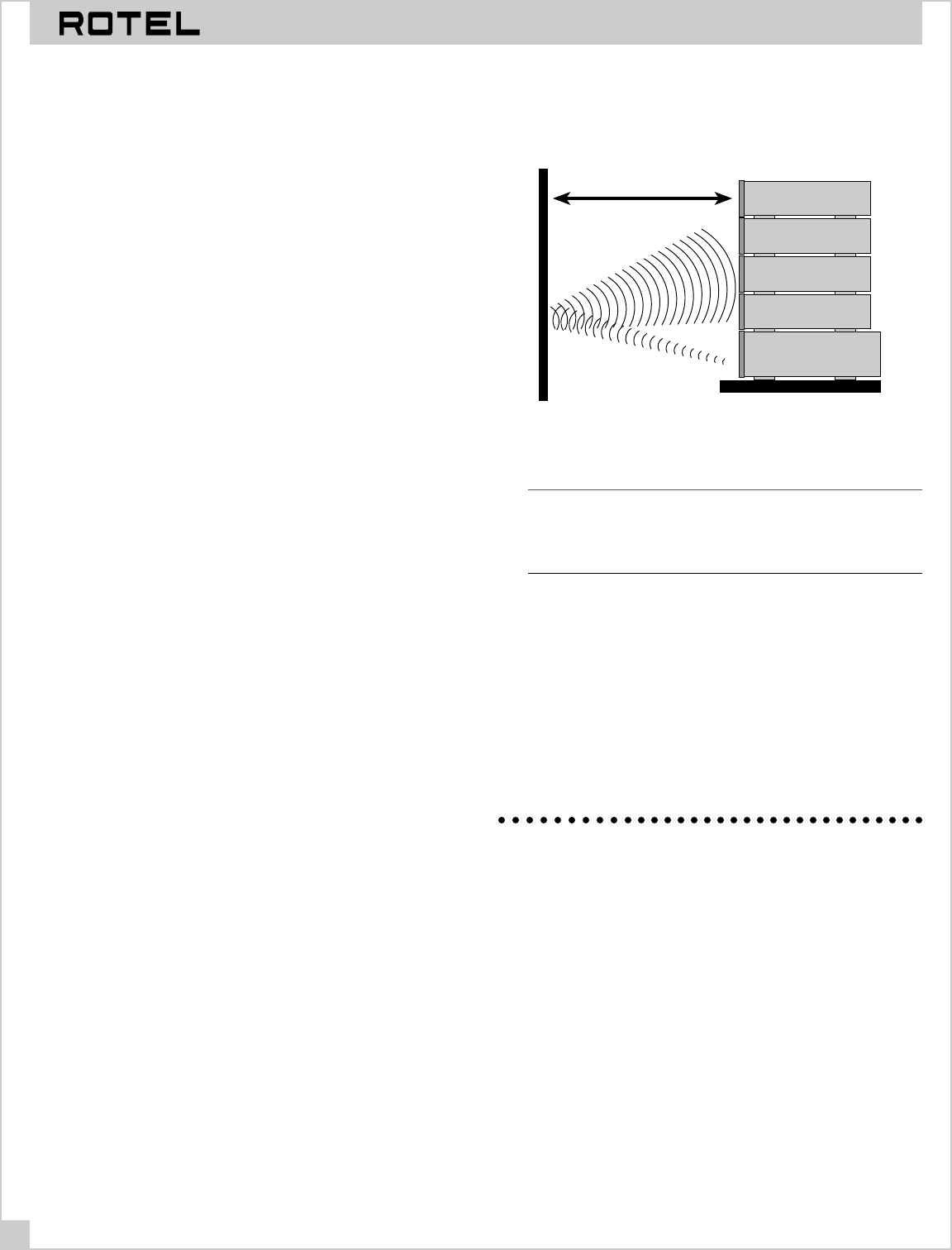
If the RMZ-955 is on an open shelf, the emitter’s signal must first
travel to an IR-reflective surface (an opposing wall, for example)
and then to the source component.
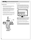
RMZ-955 controller
DVD Player
CD Player
Cassette Deck
AM/FM Tuner
20 feet or less
Keep total IR signal travel to 40' or less. Remember that it
must travel to a hard reflective surface and back again.
Note: If an RSM-901 sensor display is located in the same room
as the RMZ-955 controller, it is essential that the output form the
front-panel IR flood emitter NOT reach the RSM-901 sensor. IR
loop problems can cause intermittent operation.
IR Repeater Jacks
The RMZ-955 also has four rear panel IR output jacks for use
with industry standard IR repeaters (made by Xantech and oth-
ers). The use of these external repeaters on each source compo-
nent is ideal in situations where output from the front panel flood
IR emitter is blocked from the source components by a door, full
depth shelf, etc. It is also an ideal solution when the front panel
flood emitter output could reach an RSM-901. When IR repeaters
are used, the front-panel flood emitter can be easily disabled.
System Wiring Considerations
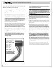
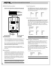
Data Cable and Connectors
The data path between the RMZ-955 controller/amplifier and
RSM-901 sensor/displays and RKP-901 keypads must be made
with cable with six insulated conductors plus a foil and/or
braided outer shield. We recommend a Belden 9536 equivalent
for best results. The RMZ-955 system data connectors work only
with cables using 24 gauge conductors. Make sure that all data
cables conform to this requirement.
Data cable termination is via industry-standard 6 pin IDC
connectors made by Methode and others. (The Methode part
number is 1300-106-424.) Data cable connection instructions are
found in the
Installation
section of this manual (see page 9).