


MULTI-ROOM SYSTEM CONTROLLER RMZ-955
12
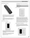
Data cable connections
Data communication to and from the RMZ-955 controller and the
remote zones’ RSM-901 sensor/displays and RKP-901 keypads is
by 6 conductor shielded cable.
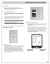
Note: One, and only one, data cable runs from the RMZ-955 to
each zone. Multiple sensor/display and keypad combinations in
one zone should be wired via series connections detailed in the
section on Zone Connection Strategies (page 15).
We recommend the use of Belden 9536 cable or the equivalent.
The Methode data connectors supplied with the RMZ-955 only
accept cable with 24 gauge conductors.
Using cable with a foil and/or braided shield is absolutely essen-
tial in maintaining data integrity over the long runs between the
controller/amplifier and a zone’s control code generating de-
vices. Make sure that the shield is firmly connected at both the
RMZ-955 and at any command device terminal.
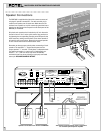
We recommend that you run each zone’s data cable and speaker
cables together to save time. There is absolutely no performance
penalty for doing so.
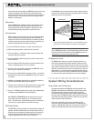
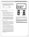
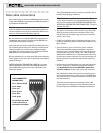
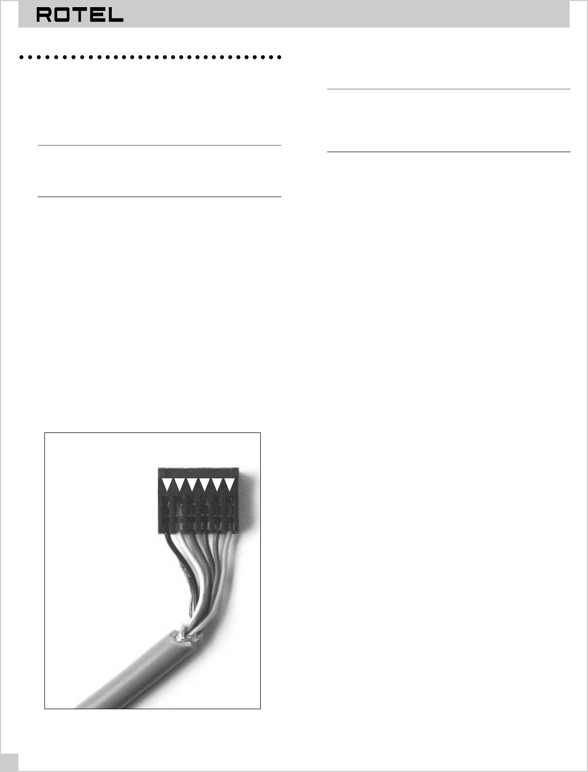
PROPER DATA CABLE TERMINATION IS CRITICAL. All connec-
tions for RMZ-955 and the remote zone’s RSM-901 sensor/dis-
plays and RKP-901 keypads use the color code shown in the
following illustration:
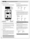
DATA CONNECTOR
WIRING CODE
Pin 1• black & shield
Pin 2• white
Pin 3• red
Pin 4• brown
Pin 5• blue
Pin 6• green
Connections are made
in the same order at
both ends of the cables.
1 2 3 4 5 6
The supplied Methode connectors need to be crimped to lock to
the data cable’s 24 gauge conductors.
Note: Do not use a screwdriver, metal ruler or knife blade to
“crimp” these connections. You may think these tools will work
but you will be mistaken. USE THE DEDICATED CRIMPING TOOL
SPECIFICALLY DESIGNED FOR THESE CONNECTORS. This tool is
available from Rotel.
• Strip about 1.5" of the outer cable insulation using a sharp knife.
Separate the outer shield from the conductors and trim it off
flush with the outer insulation, being careful not to trim off the
shield or “drain” wire.
• DO NOT strip insulation off the six individual conductors as the
connector automatically makes contact with the conductor core
when crimped.
• Place the shield or “drain” wire into slot 1 of the connector.
Then, place the BLACK conductor immediately on top of the
drain wire in slot 1, hold them both in place and push the crimp-
ing tool handle until you hear a slight “click.” Both conductors
should now be locked into slot 1. The rachet action of the crimp-
ing tool ensures proper connection. The clicking sound tells you
that the connector slot contacts have pierced the conductor’s
insulation.
• Continue the process following the color code guide above until
all other conductors are locked in the appropriate connector
slots. Remember that slot 1 is the ONLY ONE to get the drain
wire and a conductor. All other slots receive only a conductor.
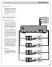
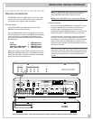
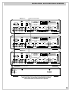
After attaching the cable conductors to the connector, insert it
into the appropriate zone’s 6 pin data terminal on the RMZ-955’s
rear panel. Be careful to center the connector over the terminal
pins before inserting.
The maximum cable length for guaranteed operation is 300'.
Longer lengths may be practical in some installations with low
RF (radio frequency) and EMI (Electro-Magnetic Interference).