


21
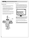
Then, using standard shielded RCA-RCA audio interconnet
cables, connect Source 1’s “loop through” outputs on the first
RMZ-955 “A” to the corresponding Source 1 inputs on the sec-
ond RMZ-955 “B”. Repeat this procedure for all four sources.
If a system requires a third RMZ-955, repeat this procedure but,
this time, connect the “loop-though” source output on the sec-
ond RMZ-955 “B” to the corresponding input on the third
RMZ-955 “C” and so for a fourth controller “D”.
NOTE: It is important to observe proper channel continuity when
connecting source components to more than one RMZ-955.
IR Connections
Systems with multiple RMZ-955 controllers follow generally the
same approach to distributing IR signals to the source compo-
nents as a single RMZ-955 system. Therefore, review the section
on IR installation, particularly on the choice of using the front-
panel flood emitter or the back-panel “remote” emitter connec-
tions.
When 2 or more RMZ-955s are used in the same system, we sug-
gest that you connect them so that only the first RMZ-955 distrib-
utes IR commands to the source components and that the IR
emitter functions of all additional RMZ-955 controllers is dis-
abled. This avoids potential interference leading to erratic
operation, particularly when using the front panel IR flood emit-
ters.
Note: This is a suggestion only and not a hard and fast rule.
There may be some unusual system layouts which benefit from
multiple RMZ-955s distributing IR to the sources. This option is
covered below as an exception to the standard practice.
The general approach to configuring IR connections for multi-
controller systems involves three steps:
a) Configure the first RMZ-955 “A” to distribute IR codes to the
sources (either through its front-panel flood emitter or its “re-
mote” IR emitters as described in the section on installing single
controller systems.
b) Disable the flood emitter on all other RMZ-955 controllers by re-
moving the “TX-Form” jumper connecting Pins 2 and 3.
c) Relay IR codes from additional RMZ-955 controllers to the first
one by installing a series of jumper wires connected to the “TX-
Form” terminal block as outlined below.
Use the following connections for multiple RMZ-955 systems:
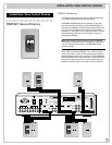
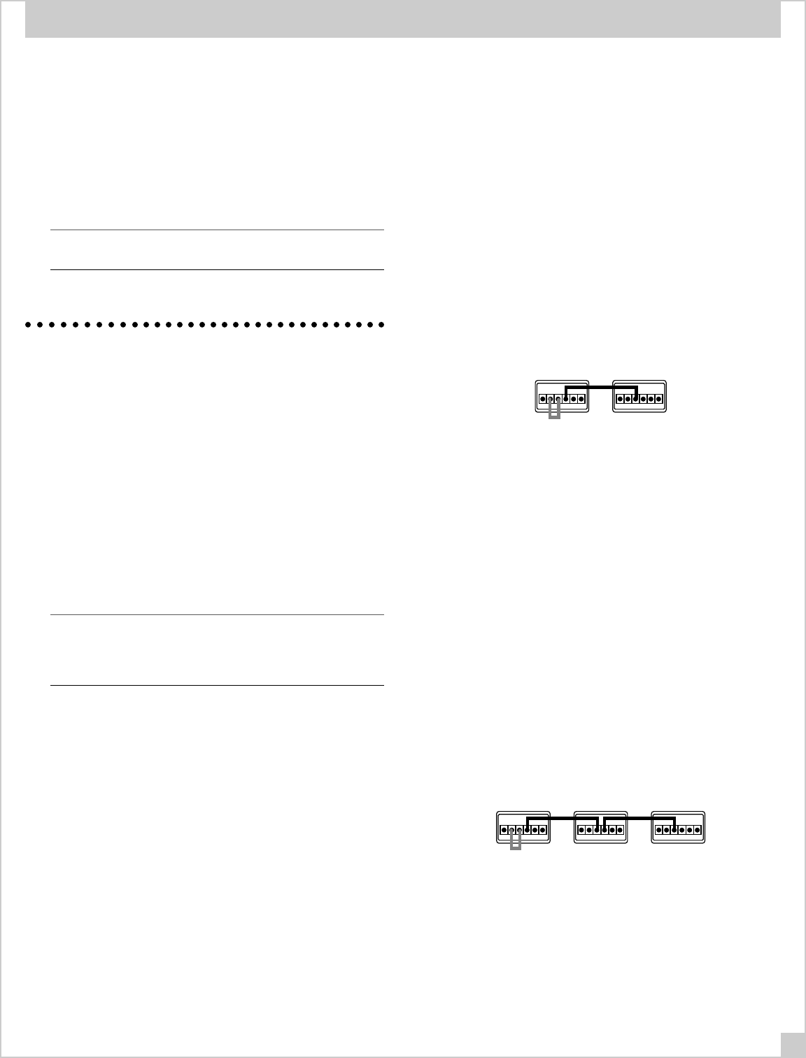
For 2 RMZ-955s (5 to 8 zones):
• Remove the jumper between terminals 2 & 3 of the TX FORMAT
block on RMZ-955 “B” to disable its IR flood emitter. Leave the
jumper in place on RMZ-955 “A” if you are using its front-panel flood
emitter. Remove the jumper if you are using remote IR emiiters con-
nected to the back panel of
RMZ-955
“A”.
• Link IR signals to the first controller by connecting terminal 3 of
the RMZ-955 “B” TX FORMAT block to terminal 4 on RMZ-955
“A”. This completes the IR signal link to the IR flood or “remote”
emitter on RMZ-955 “A”.
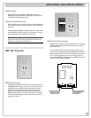
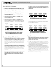
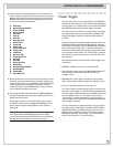
Use this jumper arrangement with 3 RMZ-955 controllers.
Disables the IR flood emitters on all but the first controller.
Remove gray jumper if using back panel IR repeaters
from the first RMZ-955 instead of the flood emitter.
TX-FORMAT
123456
TX-FORMAT
123456
RMZ-955
"A"
RMZ-955
"B"
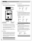
For 3 RMZ-955s (9-12 zones):
• Remove the jumpers between terminals 2 and 3 of the TX FOR-
MAT blocks on RMZ-955 “B” and “C” to disable their flood emit-
ters. Leave the jumper in place on the first RMZ-955 “A” to use
its front-panel flood emitter. Remove this jumper as well do dis-
able the flood emitter when using remote IR emitters.
• Connect terminal 3 of the RMZ-955 “C” TX FORMAT block to
terminal 4 on RMZ-955 “B”.
• Connect terminal 3 of the RMZ-955 “B” TX FORMAT block to
terminal 4 on RMZ-955 “C”. This completes the signal link to the
IR flood emitter on RMZ-955 “A” from the other two RMZ-955s.
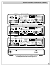
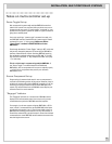
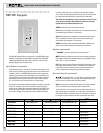
Use this jumper arrangement with 3 RMZ-955 controllers.
Disables the IR flood emitters on all but the first controller.
Remove gray jumper if using back panel IR repeaters
from the first RMZ-955 instead of the flood emitter.
TX-FORMAT
123456
TX-FORMAT
123456
TX-FORMAT
123456
RMZ-955
"A"
RMZ-955
"B"
RMZ-955
"C"
INSTALLATION: MULTI-CONTROLLER SYSTEMS