


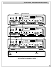
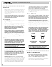
MULTI-ROOM SYSTEM CONTROLLER RMZ-955
16
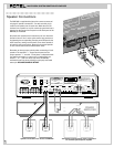
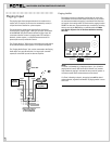
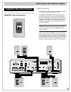
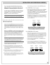
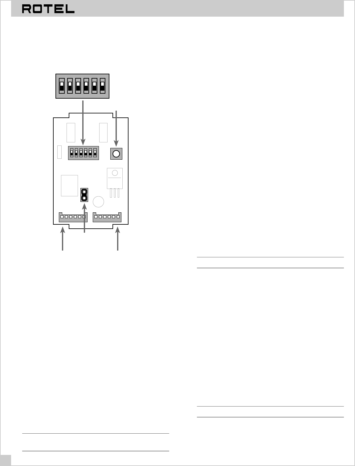
RSM-901 Data Connections
Prepare the data cable with the supplied termination plug using
the same color coding as previously described for the RMZ-955.
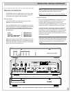
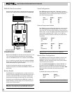
OUTIN
JP1
RESET SWITCH SW1
Press after changing
configuration
OFF
ON
123456
DIP SWITCH
See instructions for
configuration settings
OFF
ON
123456
JUMPER 1
install jumper
to enable battery
backup
INPUT DATA CONNECTOR
Connect to RKP-901 Keypad or
slave RSM-901 display/sensor
OUTPUT DATA CONNECTOR
Connect to RMZ-955
controller/amplifier
Note that each RSM-901 has two data terminals labeled “In” and
“Out” respectively. Connect the remote zone end of the data
cable from the RMZ-955 to the “Out” connector on the RSM-901.
The “In” connector is used to “daisy-chain” additional RSM-901
display/sensors or RKP-901 keypads in the same zone. See
Zone
Connection Strategies
on page 15 for details.
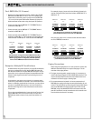
A number of configuration settings must be made using the
switches and jumpers on the back of the RSM-901. These are de-
tailed below.
Battery Enable
Each RSM-901 has a rechargeable back-up battery which main-
tains the clock and configuration information when power to the
controller is switched off. When fully charged, the battery will
then maintain the configuration information for several weeks.
The battery must be enabled when the RSM-901 is installed. To
enable the battery, place the jumper JP1 to link the two pins as
shown in the illustration above.
Note: After initial installation, leave the RMZ-955 turned on con-
tinuously for a few days to ensure that the battery is charged.
Zone Configuration
Each RSM-901 must be configured or “addressed” as being in
Zone A, Zone B, Zone C, or Zone D. You select the proper zone by
setting Switches 1 & 2 on the DIP switch shown in the illustra-
tion. Use the following settings:
Zone Switch 1 Switch 2
A (default) OFF OFF
B OFF ON
C ON OFF
DONON
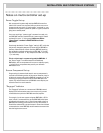
Source Component Labels
Each RSM-901 must be configured to display the correct label for
each source component. It always displays “Tuner” for source
input 1 and “CD” for source input 2. However, source input 3 can
display “Tape” or “Sat” depending on the setting of Switch 3 and
source input 4 can display “CD2”, “VCR”, “Ld”, or “DVD” de-
pending on the setting of Switch 4 and Switch 5. Use the follow-
ing settings:
Source Input 3 Switch 3
Tape (default) OFF
Sat ON
Source Input 4 Switch 4 Switch 5
CD2 ON ON
VCR ON OFF
LD OFF ON
DVD (default) OFF OFF
Note: Remember to set these switches on all RSM-901s.
Master/Slave Configuration
Each RSM-901 must be configured as a Master or Slave by set-
ting Switch 6. Because it is possible to have more than one
RSM-901 in any zone, follow the simple rules to ensure that the
required functions are available:
Each zone used in a system must have a Master RSM-901. In a
zone with more than one RSM-901, only one must be set as a
Master and each other must be set as a Slave. The Master must
be the first device on the data cable to the zone from the
RMZ-955.
The Master/Slave settings for Switch 6 are:
Master/Slave Switch 6
Master OFF (default)
Slave ON
Note: Clock and Alarm functions can only be set from a Master.