


MULTI-ROOM SYSTEM CONTROLLER RMZ-955
20
AC Power
Multiple controller systems require handling AC connections in a
way that allows any zone to “power up” or “power down” the
system. In other words, there must be a provision for zones con-
nected to additional RMZ-955 controllers to control the system’s
switched AC outlets.
A special feature of the RMZ-955, called “AC Link” simplifies the
installation of multi-controller systems with a simple control line
connection between units for AC control.
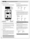
AC Connections
Plug all RMZ-955 controllers into unswitched AC outlets, provid-
ing a constant AC supply.
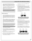
Plug all source components into the switched outlets located on
the rear panels of the RMZ-955 controllers. As in a single-con-
troller system, the recommended approach is to use a Rotel RLC-
900 power conditioner/switcher in conjunction with the first
RMZ-955’s rear panel outlets. This allows the first RMZ-955 to
handle all AC switching for the system.
With the “AC Linking” feature, it is also possible to plug source
components into any switched outlet on the rear panel of any
RMZ-955. All of these outlets are controlled in unison. When the
system is “powered up” from any zone, the switched outlets on
the first RMZ-955 and all other controllers are turned on. When a
“power down” command is sent, all RMZ-955’s go into standby
and their rear panel switched outlets are turned off.
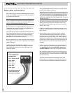
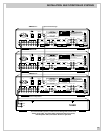
AC Link
Unified AC control in multi-controller systems is achieved by a
special “AC Link” connection from the first RMZ-955 to the sec-
ond and so on down the line. This connection uses standard 3.5
mm stereo mini-jacks at both ends of a 3-conductor cable.
Note: It is essential to use a stereo mini-jack for the “AC Link”
connection between controllers (such as Radio Shack #274-389).
Do not substitute a mono 2-conductor cable.
To make the connection, plug one end of the 3.5 mm stereo cable
into the 3.5 mm jack labeled “Link Out” on the first RMZ-955.
Then plug the other end of the cable into the jack labeled “Link
In” on the second RMZ-955. Then link the second RMZ-955 by
connecting its “Link Out” to the third RMZ-955’s “Link In” jack
with another cable. And, so on until there is an “AC Link” con-
nection between all RMZ-955 controllers.
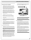
External 5V Trigger: Once you have completed all of the “AC
Link” connections, the “Link Out” connector on the last RMZ-955
is still available. This jack can provide a +5V D.C. control voltage
that could be used to activate external devices in an elaborate
custom system. When the Rotel system is activated from any
zone, this control signal goes to +5V. When the total system
“power down” command is given from any zone, the RMZ-955
controllers go into Standby mode, the rear panel switched AC
outlets are shut off, and this control signal goes to 0V.
This external trigger requires the same 3.5 mm stereo mini-jack
as the “AC Link” connections. The “tip” of the connector carries
the +5V DC control voltage.
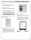
Manual AC Override
There is a provision to manually override the “AC Link” control of
the switched outlets. While not common, there may be custom
system configurations where being able to manually power up all
of the switched outlets and components connected to them.
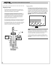
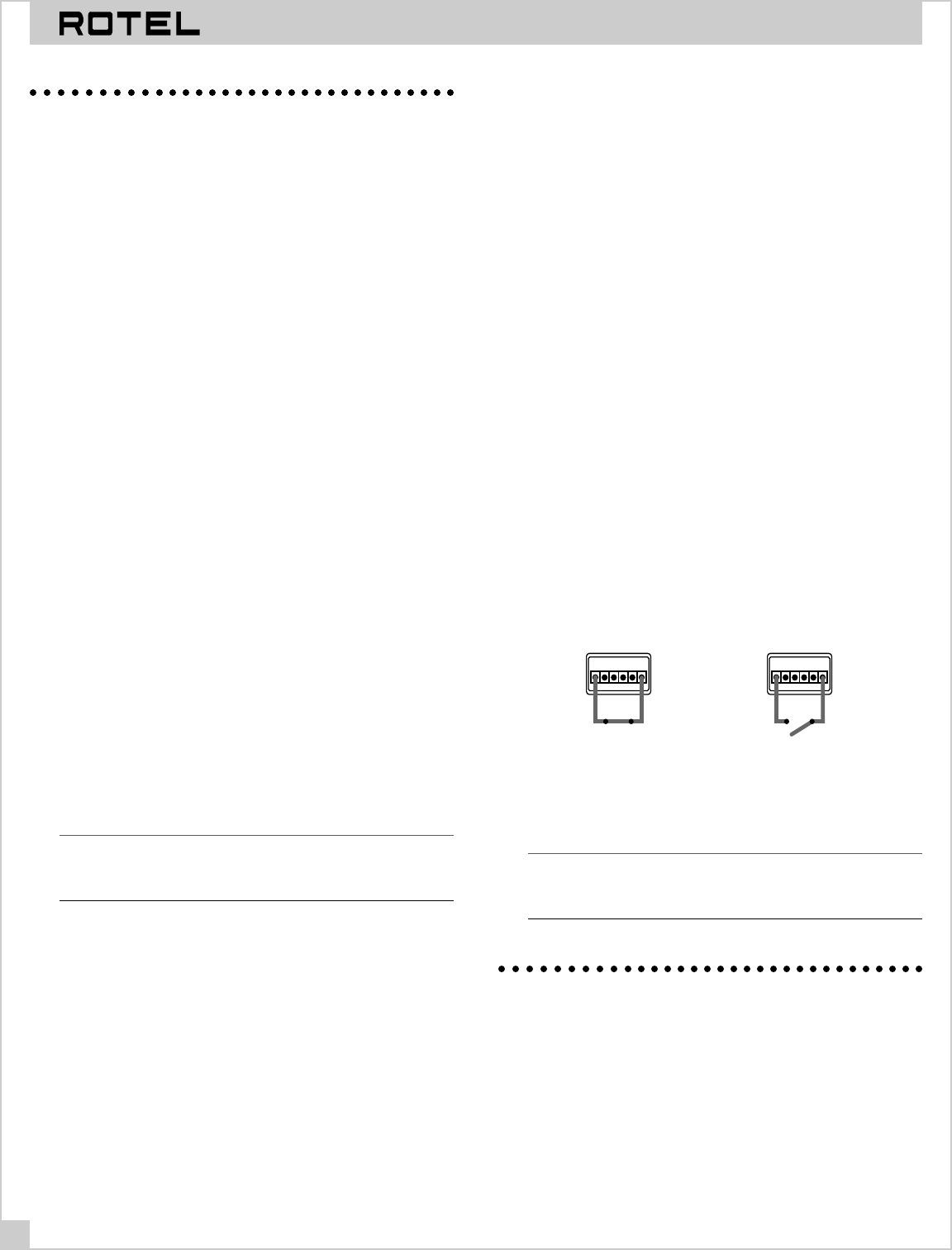
To enable the manual override, connect Pin 1 and Pin 6 of the
rear panel TX FORMAT jumper block with a jumper wire. As long
as these two pins are connected, the switched AC outlets on all
RMZ-955’s will be powered on. When the two pins are uncon-
nected, control of the AC outlets will revert to standard control
from the zones, depending on whether the system has been acti-
vated from a zone or not.
In practice, the manual override jumper described above would
be replaced with a simple single-pole switch connected be-
tween Pin 1 and Pin 6 of the “TX-FORM” block. When the switch
is closed, manual override is active. When the switch is open,
activation of the AC outlets reverts to standard zone control.
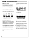
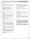
To manually turn on all
switched AC outlets, connect
pins 1 & 6 with a jumper
or closed switch
TX-FORMAT
123456
For automatic system
control of switched AC
outlets, remove jumper
or open switch
TX-FORMAT
123456
Note: In multi-controller systems, Pin 6 must be connected from
the first controller to the Pin 6 on the next, and so on daisy-
chainging all RMZ-955s to enable the manual override.
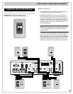
Source Connections
Multi-controller systems share the same four source compo-
nents. Therefore, it is necessary to pass the signal from each
source to all of the RMZ-955 controllers in a system.
Connect all sources to the first RMZ-955 per the instructions as
shown
Installation: RMZ-955 Controller
on page 6.