


10
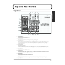
Top and Rear Panels
These adjust the [MIC IN] sensitivity. (p. 17)
10.
[PEAK] Indicators
These light up when the input level exceeds the set value. (p. 17)
11.
[PHANTOM/PHASE/LO-CUT] Buttons
These call up the Phantom power switches, plus the Phase, Lo-cut, and Attenuator setting screens. (p. 17)
12.
[EDIT CH SELECT] Buttons
These specify the channels to manipulate. Pressing them simultaneously links the effect settings for both
channels. (“Linking” (p. 28)).
13.
[BYPASS] Buttons
These bypass effects temporarily. (p. 19)
14.
[EDIT SELECT] Buttons ([MODEL] Button)
This calls up the editing screen for microphone modeling. (p. 19)
15.
[EDIT SELECT] Buttons ([EQ] Button)
This calls up the parameter screen for the equalizer. (p. 20)
16.
[EDIT SELECT] Buttons ([DYNAMICS] Button)
This calls up the parameter screen for dynamic effects. (p. 21)
17.
[EDIT SELECT] Buttons ([PLUG IN] Button)
This calls up the editing screen for plug-in effects. (p. 24)
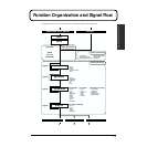
Rear Panel
1.
[POWER] Switch
This switches the power on and off. (p. 13)
2.
[AC IN] Connector
This is for connecting the power cable. (p. 12)
3.
[DIGITAL OUT AES/EBU] Jack
This is an AES/EBU-standard digital-output jack.
4.
[DIGITAL OUT] Jack
This is an S/PDIF-standard digital-output jack.
5.
[DIGITAL IN] Jack
This is an S/PDIF-standard digital-input jack.
6.
[USB] Jack
This is for connecting a computer and exchanging parameter settings using MIDI protocol. (p. 30)
7.
[OUTPUT LEVEL] Switch
This switches the output level to either -16 dBu or +4 dBu. (p. 13)
8.
[LINE OUT] Jack
This is a balanced XLR-type line-output jack. (p. 13)
12 34 67 85
12 34 67 85