


WWW.POLKAUDIO.COM/AMPS 9
8
PA 12V AMPLIFIERS
ENGLISH
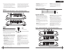
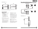
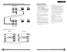
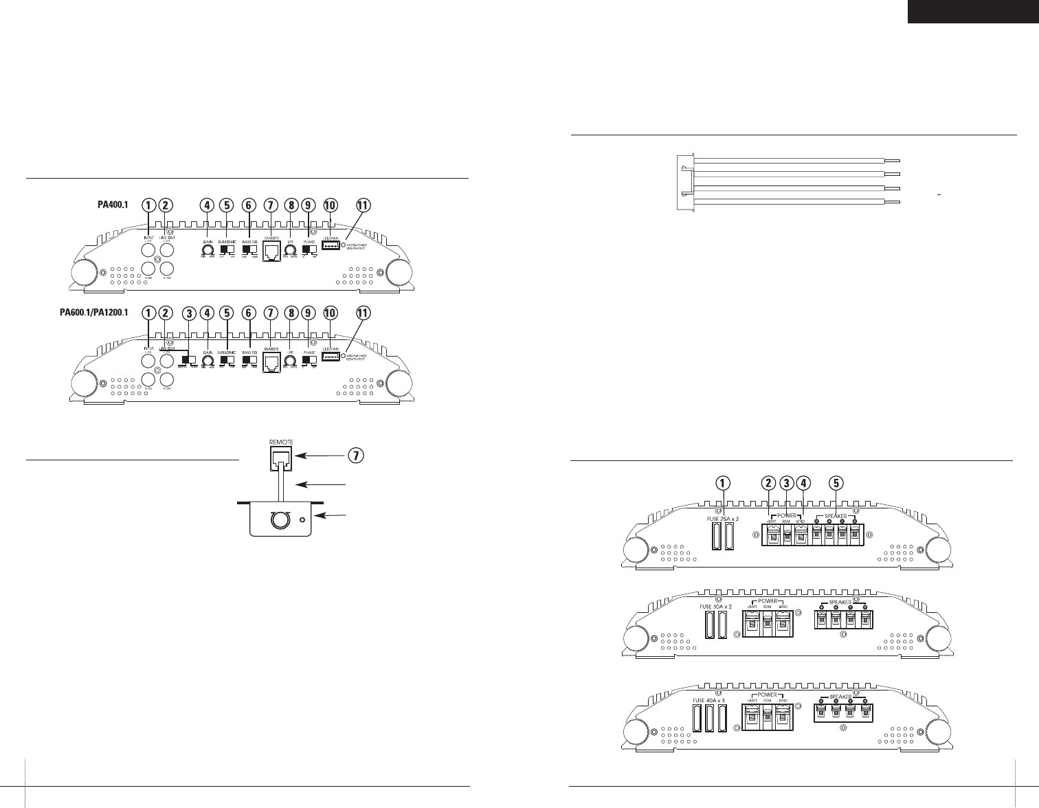
REAR PANEL CONNECTIONS
1.Fuses—These fusesprotect theamplifier against
internalelectrical damageand aremeant toprotect
theamplifier only.All otherpower connectionsshould
befused atthe source. ThePA400.1 uses2-25A fuses,
thePA600.1 uses 2-30A fusesand thePA1200.1 uses
3-40Afuses.
2.(+) 12Volt Power—Connectthis terminalthrough a
FUSEor CIRCUITBREAKER to thepositive terminalof
thevehicle batteryor thepositive terminalof anisolated
audiosystem battery.
WARNING:Always protectthis powerwire byinstalling
afuse or circuitbreaker ofthe appropriatesize within
12inches of thebattery terminalconnection.
3.Remote TurnOn—This terminalturns onthe amplifier
when(+) 12 volt is applied toit. Connectit tothe remote
turnon leadof thehead unitor signalsource.
4.Ground—Connect thisterminal directlyto thesheet
metalchassis of thevehicle, usingthe shortestwire
necessaryto makethis connection.Always usewire of
thesame gaugeor largerthan the(+) 12volt powerwire.
Thechassis connectionpoint should be scraped freeof
paintand dirt. Useonly quality crimpedand/or soldered
connectorsat bothends ofthis wire.DO NOT connect
thisterminal directlyto thevehicle batteryground
terminalor anyother factoryground points.
5.Speaker Terminals—Connectsubwoofers tothese
terminals.(Refer tothe SpeakerWiring Diagrams
sectionof thisguide.)
FIGURE 3—AMPLIFIER CONNECTIONS—REAR (PA400.1/PA600.1/PA1200.1)
PA400.1
PA600.1
PA1200.1
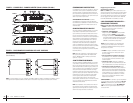
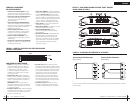
FIGURE 2—LED/FAN HARNESS
BLACK
BLUE
BLACK
RED
_
+
_
+
TO LEDs
TO FAN
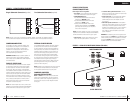
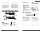
FRONT PANEL CONNECTIONS/CONTROLS
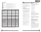
1.RCA InputJacks—Accepts linelevel outputsfrom
headunits orsignal processorsat voltages between
150mVand 7.5 volts.
2.RCA LineOutput Jacks—Thesepass through
RCAjacks canbe used to sendthe inputsignal to
asecond amplifier.
3.Slave/Master Switch—Controlswhether the
amplifieris aslave ormaster whenconnected in
combinedamplifier configurations.(Refer tothe
CombinedAmplifiers sectionof this guide.)
4.Gain Control—Controlsthe amplifier’ssensitivity
andis usedto match theinput levelof theamplifier
tothe outputlevel of the signalsource.
5.Subsonic Switch—Thesubsonic filterattenuates
frequenciesbelow 30Hzby 24dBper octave.
6.Bass EQSwitch—Adds 8dBof bassboost tothe
subwooferwhen selected.
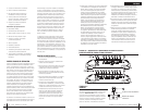
7.Remote—Controls thesubwoofer amplifiergain,
froma remotelocation forease ofadjustment
duringlistening.
Warning:DO NOTconnect alevel controlknob from
othermanufacturers tothe RemoteSub LevelControl
ofany PolkAudio amplifier.Even thoughthe connectors
fitproperly, thecontrol knoband connectorpin positions
maybe differentand theamplifier willbe damaged.
8.LPF Control—Controlslow passfilter cutofffrom
30Hzto 250Hz.
FIGURE 1a—
AMPLIFIER CONNECTIONS/CONTROLS—FRONT (PA400.1/PA600.1/PA1200.1)
10.Battery and groundconnections tothe vehicleshould
bemade withcrimped ring terminals of theappropriate
size(surface area is whatcounts;) solderingthe termi-
nalsafter crimping isalso recommended.
11.Due tothe high-frequencyMOSFET switchingpower
supply,filtering thepower cableis notgenerally required
(rememberthat theamp can’tdeliver fulloutput if the
powersupply is restricted.)Proper groundingof the
signalsource is mandatory forthe amplifierto reach
itsperformance peak. Ifthe RCAinputs arenot grounded
adequatelyvia thesignal source,electrical noise from
thevehicle maybe pickedup inthe system.
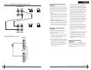
FIGURE 1b—
REMOTE
Remote—Controlsthe subwoofer amplifiergain, from
aremote locationfor easeof adjustment duringlistening.
Warning:DO NOTconnect alevel controlknob fromother
manufacturersto theRemote SubLevel Controlof anyPolk
Audioamplifier. Even though theconnectors fitproperly,
thecontrol knoband connectorpin positionsmay bediffer-
entand theamplifier willbe damaged.
9.Phase Switch—0°or 180°selectable forswitching
thephase output to the woofer.
10.LED/FAN Connector—Allows connectionof an
optionalcooling fanfor theamplifier.
11.Status LED—Will illuminateGREEN toindicate the
amplifieris onand operatingnormally, andwill be
illuminatedRED if theamplifier shutsdown dueto
shortcircuit, DCoffset, oroverheating detectedby
onboardprotection circuitry.
Phone Line Cord
Remote Volume Module