


C2900M-B (1/03) 31
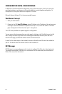
CONNECTING DATA TERMINALS
The NET104A has a serial interface that can be configured on the Interface Settings configuration
page for terminal control or transparent data: RS-232 or RS-485, etc.
Use As Control Terminal Port
For local control and configuration of the unit, you can connect a data terminal (for example, a PC
running a standard terminal program) to the serial interface labeled COM on the NET104A. The
9-pin D-sub connector can be connected to a PC’s COM port.
You can use a standard terminal program to communicate with the unit. The default parameters are
set to 19200 baud, 8 bits of data, 1 stop bit, and no parity (8N1).
To access the online help, type ? (a question mark) in the terminal window. For more information on
the command set, see the
Configuration
section. This mode allows the control port to be used to
send serial data that requires flow control.
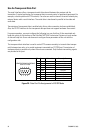
You can configure the RS-485 half-duplex mode in the web browser. The RTS and CTS signals are
enabled for flow control.
If this RS-485 mode is chosen, the camera control data is transferred to this port. Certain cameras
with fixed data length require the buffered RS-485 mode. (This half-duplex mode is not required for
interfacing to any Pelco product.)
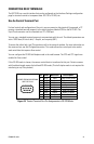
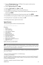
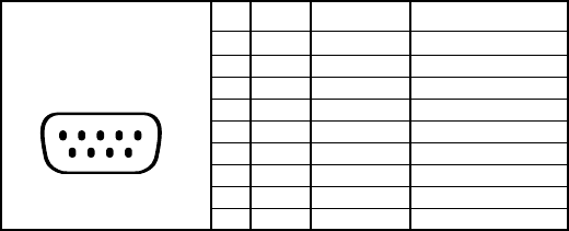
Figure 19. Control Terminal Port Pin Assignments in RS-232 Mode
1 2 3 4 5
6 7 8 9
VIEWED FROM SOLDERING
SIDE OF PLUG
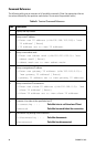
Pin Name Direction Description
1 DCD Input Data Carrier Detect
2 RXD Input Receive Data
3 TXD Output Transmit Data
4 DTR Output Data Terminal Ready
5 GND Ground
6 DSR Input Data Det Ready
7 RTS Output Ready To Send
8 CTS Input Clear To Send
9– – –