8
Outlaw Audio
Owner’s Manual
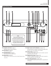
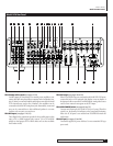
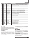
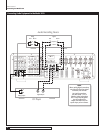
Model 1070 Rear Panel
The Model 1070 rear panel provides a wide range of digital and analog inputs
and outputs. Many current components provide multiple types of audio and
video connectors. When in doubt about which to use, choose the best available
connection based on the following: For video, the highest quality signal is
obtained by using DVI/HDMI, followed by component, S-Video and composite.
For audio, start with either a coaxial or optical digital cable, otherwise use
standard RCA-type analog connectors.
In some cases you will want to make more than one type of connection for added
flexibility in configuring your system. Those situations will be noted below.
RP1 Component video inputs (see pages 17-25)
Use these three sets of jacks to connect devices with component video
outputs, such as a DVD player or a digital TV tuner. If the device has a
DVI or HDMI output, use that connection instead.
RP2 FM antenna input (see page 20)
Accepts a 75-ohm coaxial cable. Use it to connect the supplied FM
antenna.
RP3 AM antenna input (see page 20)
Use this to connect the supplied AM loop antenna or any other external
AM antenna.
RP4 Component video output (see pages 17-25)
Connect to a video display that accepts component video. If the device has
a DVI or HDMI input, use that connection instead.
RP5 DVD input (see pages 17-25)
Use this group of inputs to connect a device with analog multi-channel
outputs, such as a DVD-Audio or Super Audio CD player. The composite
and S-Video jacks are specifically designated for use with this input,
or you may assign any of the DVI or component video inputs. A pair of
analog audio inputs is also provided.
RP6 Bass Management selector switch
Three position toggle switch for selecting how the Model 1070 routes
bass signals for the DVD 7.1 multi-channel analog inputs only. Choices
are “Digital” (which applies the choices that you’ll make in the Speaker
Size and Speaker X-Over sub-menus), “Bypass” (no bass management at
all) and “HPF/LPF” (a fixed analog crossover at 80Hz). Bass Manage-
ment parameters are set for all other inputs using the Speaker Size and
Speaker X-Over sub-menus explained on pages 30-31.
RP7 IR input
Connect an external infrared sensor to this input to allow remote control
of the Model 1070 even if it is installed in a cabinet with solid doors. It also
allows control of the Model 1070 from a second room.
RP8 IR output
Feeds an infrared flasher attached to another piece of audio/video gear.
Any infrared remote signal received by the Model 1070’s front-panel
sensor or by an external sensor connected to the Model 1070 will be
relayed through this jack, so concealed audio/video devices can be
controlled by remote.
RP9 12V Trigger output (see page 23)
This jack provides a 12-volt DC output whenever the Model 1070 is
switched on. Usually, this jack is used for automatic turn-on of a com-
patible amplifier equipped with a DC trigger input.
RP10 Serial number
Write this number in the space provided on page 4 for future reference.
RP11 RS-232 port (see page 23)
Use this connector for uploading new software into the Model 1070.
RP12 Digital audio inputs (see pages 15-25)
Optical and coaxial inputs for connecting digital audio devices such as
DVD players, CD players, and digital TV tuners. These inputs are assign-
able to any video or audio source.
RP13 Reset switch access
Together with the RS-232 port, this switch is used to enable the software
update process of the Model 1070. This switch should not be confused
with resetting the Model 1070 configuration settings to their factory
defaults which is explained on page 49.
RP14 Digital audio outputs (see pages 17-25)
Connect these to a CD recorder, MiniDisc recorder, a computer or any
other audio recording device that accepts digital inputs. Both optical and
coaxial outputs are provided.
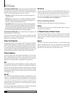
RP15 Loudspeaker outputs (see pages 20, 22 and 23)
Five-way binding posts for connecting speakers to the Model 1070’s
internal amplifiers. Connections are provided for Left, Right, Center,
Surround Left, Surround Right, Surround Back Left, and Surround
Back Right channels.
RP16 Speaker impedance selector switch
Set this switch to match the impedance of the speakers connected to the
Model 1070. Configures the power supply for optimum performance.
RP17 Analog audio connections (see pages 15-25)
This group includes input connectors for analog audio devices, such as
cable boxes, laserdisc players or older CD players. There is also a tape
loop for feeding an analog audio recorder or cassette deck.
RP18 Video 1 connections (see pages 15-19, 25)
Connect these audio and video jacks to a VCR or a DVD recorder. If the recorder
has an S-Video input, use that connection instead of composite video.
RP19 Video 2 and 3 connections (see pages 17-25)
Connect these two sets of audio and video jacks to video devices, such
as DVD players, satellite receivers, regular and S-VHS VCRs, cable boxes
or laserdisc players.
RP20 Monitor out connections (see pages 20, 21 and 25)
Connect these audio and video jacks to your TV or monitor. Use the
S-Video or composite connectors when the display does not have a com-
ponent or DVI/HDMI video input.
RP21 Subwoofer output (see pages 23-25)
Connect to the input of a powered subwoofer or to an amplifier that feeds
a passive (non-powered) subwoofer. The output of the signal at this jack
is determined by the settings in the Speaker Size and Speaker X-Over
sub-menus explained on pages 30-31.
Model 1070 Rear Panel


