


15
Model 1070 7.1 Channel Surround Sound Receiver
Owner’s Manual
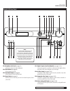
Connecting Your Model 1070
Connecting Your Model 1070
Before connecting your Model 1070 to other system components, please observe
the following simple precautions:
Don’t plug the power cord into your Model 1070 until you’ve made all other
connections.
Always pay attention to the warnings, options, and specific procedures contained
in the instructions that came with the component you’re connecting.
For analog connections, remember that:
red input jacks = right channel audio
white input jacks = left channel audio
yellow input jacks = composite video
Insert all plugs and connectors securely. If you don’t, you may experience noise,
poor performance, or equipment damage.
Don’t bundle audio/video connection cables with power cords and speaker cables.
To get the performance you expect, run all the power cords down one side of the
cabinet, all the signal connections down the other side, and the speaker cables
down the center.
You may want to use digital and analog connections to and from the same
component. This will give you additional flexibility as you configure your
system, particularly when you use an analog audio recorder.
When using an optical input or output jack, always use a high-quality optical
fiber cable.
Connect your speakers after you’ve connected all your other components to the
Model 1070 but before you plug in the power cord.
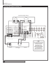
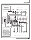
Given the wide variety of components and many ways you can connect them,
you might find initial set-up a bit intimidating. Don’t worry. The following
diagrams will guide you through the maze. They graph some of the more com-
mon situations you might encounter. Rest assured, however, that there would
most likely be several ways to connect a component so these diagrams are not
hard and fast blueprints. (Please remember to consult the owner's manual that
came with the component you are connecting for more information.)
In order to alleviate potential confusion, there is a chart on page 25 so you can
record each connection (which output to which input, etc.) as you connect your
system’s components. These connections might change as you get further into
your system configuration and we suggest that you make a few photocopies of
that page (or print a few copies of the page from the PDF version of this manual,
which is available from our website) to use as worksheets before you start. When
you’re done and your system is functioning properly, you can enter the final
connections into the manual itself for a more permanent record.
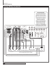
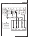
Connecting Audio Components
CD Player or Music Server
Analog
Connect the L and R channel outputs on the CD player or music server
to the CD input jacks (
RP17
).
Digital
If your CD player or music server has a digital output, connect it to one
of the coaxial or optical inputs (RP9) depending on the type of connector used
by the source. (You’ll configure the Model 1070 later to use the input you’ve
chosen. For now, note that digital input on your system chart.)
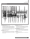
Audio Recorder
(Cassette deck, MD recorder, DAT, CD recorder, etc.)
Analog
Connect the L and R audio outputs on the recorder (usually marked
PLAY) to the TAPE IN jacks (
RP17
). Connect the L and R audio inputs (usually
marked REC) to the RECORD OUT/TAPE jacks (
RP17
).
Digital
Connect your recorder’s digital output jack to either the coaxial or
optical input (
RP12
) depending on the type of connector used by your recorder.
(As with the digital CD input, configuration will come later. For now, just note
that input on your system chart.)
If your recorder has a digital input jack, connect it to either the coaxial or opti-
cal output (
RP14
) depending on the type of connector used by your recorder.
(Configure this later, but note the connection now.)
Computer sources
NOTE: Although you can connect a computer via analog or digital
inputs, we suggest a PCM, Dolby Digital or DTS connection when pos-
sible for the best sound. You can also use your computer to record
sound from the other devices connected to the Model 1070.
Analog
Using a 1/8” (3.5mm) stereo miniplug to dual-RCA adapter cable (a
“Y” cable with male connectors at both ends), connect the computer sound
card’s audio output minijack to the TAPE IN jacks (
RP17
). Then, using a sec-
ond “Y” cable, connect the sound card’s audio input minijack to the RECORD
OUT/TAPE jacks (
RP17
).
NOTE: If you have to make a choice between connecting another
recording device or your computer through analog connections, opt to
use the analog jacks for the other recording device.
Digital
Connect your sound card’s digital output jack to either the coaxial or
optical input (
RP12
) depending on the type of connector used by the sound
card. (As with the digital CD input, configuration will come later. For now, just
note that input on your system chart.)
If your sound card has a digital input jack, connect it to either the coaxial or
optical output (
RP14
) depending on the type of connector used by the sound
card. (You’ll configure this later but note the connection now.) Note, however,
that the signal must be output from the computer in a form that is compat-
ible with the Model 1070’s signal processing, such as Dolby Digital, DTS or
conventional PCM. Other digital audio formats such as MP 3 may not be used
directly with the Model 1070.
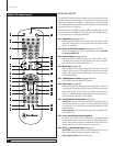
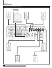
MP3 Player
Analog
You can use any analog audio input to connect an MP3 player to the
Model 1070 but you’ll probably find it most convenient to use the Left and Right
channel analog audio jacks on the front panel Video 4 input (
FP20
). Use the
same 1/8” (3.5mm) stereo miniplug to dual-RCA adapter cable (a “Y” cable
with male connectors at both ends) that we’ve suggested above to go from the
MP3 player’s headphone output to the Model 1070. Remember the color-coding
on the RCA end of the cable – red for right, white for left.