


20
Outlaw Audio
Owner’s Manual
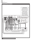
Component
If your device has component video outputs, connect them to
the component Video 1-2 input jacks (
RP1
). As you make this connection,
remember to “follow the alphabet.” (See DVD player above if you don’t remem-
ber what this means.)
DVI/HDMI
If your device a DVI or HDMI video output and your video monitor
has a DVI or HDMI input, connect the device to the DVI 1 or 2 input (
RP23
).
(For HDMI-equipped components, use either an interconnect cable with one
type of connector on each end [preferred] or an HDMI-to-DVI adapter.)
Audio Connections
Analog
Using a pair of RCA-to-RCA audio cables, connect your device’s L and
R channel analog audio outputs to the Video 1-3 analog audio jacks (
RP18
or
RP19
).
Digital
Connect your device’s digital audio output (coaxial or optical) to one
of the digital inputs (
RP12
). Note the selected input on your worksheet for
configuration later.
NOTE: Particularly with digital cable set top boxes, we recommend
that you make both an analog and digital audio connections. This will
enable the Model 1070 to revert to analog audio when you switch
away from a digital channel to one that only has analog audio. (See
page 19)
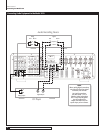
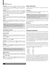
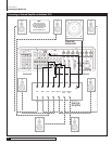
Video Display Connections
Connect a video display device (a TV, projector, etc.) to the Model 1070 using
the following methods.
Video Connections
Composite
Using a video cable with yellow RCA jacks at both ends, connect
the display device’s composite video input to the Model 1070’s composite Moni-
tor Out jack (
RP20
).
S-Video
Using an S-video cable, connect the display device’s S-video input to
the S-Video Monitor Out jack (
RP20
).
Component
If your display device has component video inputs, connect
them to the component Monitor Out jacks (
RP4
). Once again, “follow the
alphabet.”
DVI/HDMI
If your display device has a DVI or HDMI video input, connect it
to the DVI Out connection (
RP24
). (For HDMI-equipped components, use an
HDMI-to-DVI adapter.)
NOTE: The Model 1070's on-screen display does not appear at the
DVI OUT jack. Use a component, S-Video, or composite video connec-
tion to your video display device in addition to the DVI connection.
Audio Connections
Analog
If your display device has an internal tuner with an analog audio
output, connect the L and R channel outputs to the Video 1-3 analog audio
inputs (
RP18
or
RP19
).
Digital
If your display device has a digital audio output, connect it to one
of the coaxial or optical input jacks (
RP12
). Note the selected input on your
worksheet for configuration later.
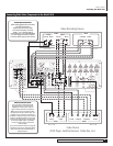
Antenna Connections
The Model 1070 has an internal AM/FM tuner with separate connections for
each band’s antenna.
FM Antenna
Connect the supplied FM dipole antenna by pushing the antenna’s coaxial
connector onto the FM antenna connector (
RP2
.)
NOTE: The supplied FM antenna is for indoor use only. For best
reception, fully extend the antenna and experiment with its position-
ing to get the strongest signal. You can attach it to a wall or other
surface using push-pins, tacks, or small nails.
If FM reception is poor with the supplied indoor antenna, we recommend
using an amplified indoor or a high-gain outdoor antenna. Connect these
antennas in the same way.
AM Antenna
Connect the supplied AM antenna to the rear panel push terminals (
RP3
).
Press one lever on the bottom of the terminal block and insert one of the
antenna wires. Release the lever and repeat the process with the other wire
and lever. Experiment with the antenna's position to obtain the strongest
signal.
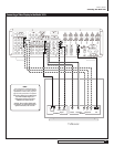
Loudspeaker Connections
The connections between your Model 1070 and your system’s main channel
loudspeakers are critical to good sound. Although there’s a lot of debate about
the “best” speaker wire and the “best” connectors, our advice is to use what
you feel is appropriate. There is one guideline, however, that we do feel is vital:
If the run from your Model 1070 to a speaker is less than 40 feet, use speaker
wire with a conductor diameter that’s identified as “16 gauge” or lower. For
longer runs, use a minimum of 14 gauge wiring. When connecting speaker
wire to each side of a speaker “pair” (e.g. front left/right, surround left/right
or surround back left/right) we recommend that the speaker wire lengths be
as close to identical as possible.
If you’re confused by the “gauge,” you’re not alone. The standard in wire
measurements is called AWG, or American Wire Gauge. The AWG number
refers to the diameter of one conductor only (speaker wire has two conduc-
tors) and smaller gauge numbers mean larger conductors. Here’s a short list
of gauge numbers and their corresponding diameters:
12 gauge .0808"
14 gauge .0641
"
16 gauge .0508
"
18 gauge .0402
"
22 gauge .0254
"
24 gauge .0201
"
You can see that “hardware store” 22 or 24 gauge wire is very thin. We don’t
recommend it for any serious audio application. Even 18 gauge “zip cord”
(also called “lamp cord”) is not that substantial. 16 gauge is our minimum
recommendation. 14 gauge is better. 12 gauge is excellent but is comparatively
hard to work with (it usually doesn’t bend easily and terminations – lugs or
banana plugs – are problematic.) The advantage of large diameter wire is that,
all else being equal, it has less resistance to current flow than thin wire.
Connecting Your Model 1070