


Masterpage:Right0
Filename [TH-R1R3EK_05Name.fm]
Page 13Friday, 8 April 2005 16:00
13
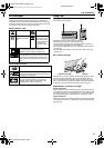
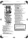
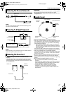
INSTALLING YOUR NEW UNIT
It’s essential that your unit be properly connected.
1 Place the unit on a stable, horizontal surface.
2 Connect the unit to a TV depending on the TV and cables you
use.
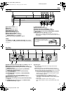
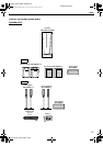
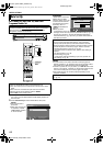
8 Basic Connection
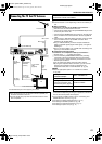
To connect to a TV with 21-pin SCART input connector ^
A Disconnect the TV aerial cable from the TV.
B Connect the TV aerial cable to the [TV ANTENNA IN] connector
on the rear panel of the unit.
C Connect the [TV ANTENNA OUT] connector on the rear panel
of the unit and the TV’s aerial connector with the supplied RF
cable.
D Connect the [L-1 INPUT/OUTPUT] connector on the rear panel
of the unit and the TV’s 21-pin SCART connector with a
supplied 21-pin SCART cable.
● The [L-1 INPUT/OUTPUT] connector accepts and delivers
either a composite signal (regular video signal), Y/C signal or
RGB signal.
● Set your TV to the VIDEO, Y/C, or RGB mode according to the
type of your TV’s SCART connector.
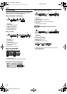
8 Component Video Connection
To connect to TV’s component video input connectors ^
A Perform steps A - C of ABasic ConnectionB.
B Connect the unit’s [COMPONENT VIDEO OUT (Y/P
B
/P
R
)]
connectors to the TV’s component video input connectors.
C Connect the unit’s [AUDIO OUTPUT] connectors to the TV’s
AUDIO input connectors.
● You can obtain high-quality component video pictures.
● By using the component video connection, you can view the
images in the progressive mode. For switching to the
progressive mode, refer to AScan Mode SetB (A pg. 76).
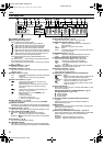
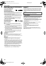
NOTES:
● Select an appropriate option of AL-1 OUTPUTB as follows
(A pg. 68):
When the setting selected is not in accordance with the TV
connected and depending on the type of appliance connected to
the unit, the correct picture will not appear.
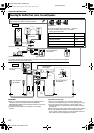
● If you possess a satellite receiver, refer to AConnecting To A
Satellite ReceiverB as well. (A pg. 70)
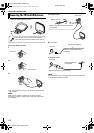
● Connecting the FM and AM antennas (A pg. 14)
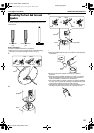
● Connecting the satellite speakers (A pg. 16)
● Connecting the powered subwoofer (A pg. 17)
● Connecting the power cord (A pg. 17)
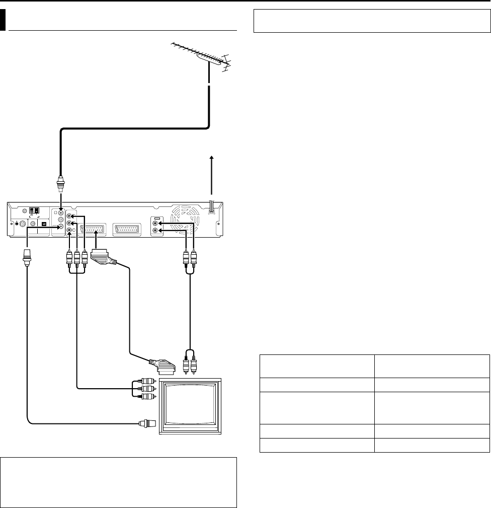
Connecting The TV And TV Antenna
ATTENTION:
● Your TV must have a 21-pin AV input connector (SCART) for
the basic connection to the unit.
● Connect the AC plug only after all connections to the TV has
been completed.
IN
OUT
RIGHT
LEFT
TV aerial cable
Mains outlet
Back of unit
Component
video cable
(not supplied)
TV
Mains power
cord
Audio
cable
(not
supplied)
To
[COMPONENT
VIDEO OUT
(Y/P
B
/P
R
)]
To [AUDIO
OUTPUT]
To [TV ANTENNA IN]
To [TV
ANTENNA
OUT]
RF cable
(supplied)
To [L-1 INPUT/
OUTPUT]
21-pin SCART
cable
(supplied)
To 75 ohm terminal
THESE STEPS MUST BE COMPLETED BEFORE ANY VIDEO
OPERATION CAN BE PERFORMED.
When your TV’s SCART
connector accepts:
Set AL-1 OUTPUTB to:
Composite signals ASCART VIDEOB
Y/C signal (separated
luminance (brightness) and
chrominance (colour) signals)
ASCART S-VIDEOB
RGB signal ASCART RGBB
Component video signal ACOMPONENTB
TH-R1R3EK_00.book Page 13 Friday, April 8, 2005 4:00 PM