


Masterpage:Right0
Filename [TH-R1R3EK_05Name.fm]
Page 7Friday, 8 April 2005 16:00
7
INDEX
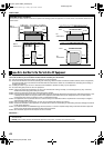
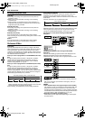
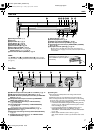
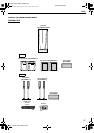
Front View
A Standby/On Button (A)
B Disc tray
C Eject Button (M) A pg. 5
D Play Button (I) A pg. 24
E Stop Button (o) A pg. 24
F Record Button (R) A pg. 38
G Enter Button (ENTER) A pg. 27
H Volume Button (VOL +/–) A pg. 25
Selection Keys (FGDE) A pg. 27
I Audio Source Button (SOURCE) A pg. 43
NOTE:
The ENTER button (G) and selection keys (H) on the unit can
only be used for ALocating A Desired Scene Using The DVD MenuB
(A pg. 27).
J Remote Sensor A pg. 9
K Front Display Panel A pg. 8
L Headphone Terminal [PHONES] A pg. 25
M S-video Input Connector [S-VIDEO] A pg. 66
N Video/Audio Input Connectors [VIDEO/AUDIO (L(MONO)/
R)] A pg. 66
O DV Input connector [DV IN (A*)] A pg. 64
* A (i.Link) refers to the IEEE1394-1995 industry specification and
extensions thereof. The
A logo is used for products compliant with the
i.Link standard.
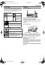
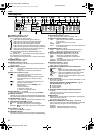
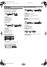
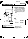
Rear View
A FM Antenna Input Connector [FM 75 K COAXIAL] A pg. 14
B AM Antenna Input Connector [AM LOOP] A pg. 14
C VHF/UHF Antenna Input/Output Connectors [TV ANTENNA
IN/OUT] A pg. 13
D Component Video Output Connectors [COMPONENT
VIDEO OUT (Y/P
B
/P
R
)] A pg. 13
E L-1 Input/Output Connectors [L-1 INPUT/OUTPUT]
A pg. 13, 67, 68, 70
F L-2 Input/Decoder* Connector [L-2 INPUT/DECODER]
A pg. 67, 68, 70
* The decoder function of this unit is not available in the U.K.
G Audio Output Connector [AUDIO OUTPUT] A pg. 13
H AC Power Cord A pg. 17
I Subwoofer Connecting Terminal [TO SP-PWR1/SP-PWR3]
A pg. 17
J Digital Audio Input Connectors [L-1/L-2 DIGITAL INPUT
(COAXIAL/OPTICAL)] A pg. 17
K Cooling Fan
● This prevents the temperature from rising inside the unit.
Do not remove it.
● Install the unit so as not to block the area around the fan.
● The unit may become hot when it is turned off, as the cooling
fan on the rear of the unit is not activated. However, the cooling
fan may be activated in the following cases;
^ In the Automatic Satellite Programme Recording standby
mode (A pg. 53), slightly before the starting time of VPS/
PDC recording (A pg. 49).
^ If you connect the decoder or satellite receiver to [L-2
INPUT/DECODER], and if AL-2 SELECTB is set to
ADECODERB, ASAT VIDEO/RGBB or ASAT S-VIDEO/RGBB.
(A pg. 69)
^ When AJUST CLOCKB is set to AONB (A pg. 81)
(Set AJUST CLOCKB to AOFFB if you mind the noise of the
fan.)
VOL
SOURCEENTER
PHONES DVIN
INPUT F1
VIDEOL(MONO) AUDIO
R
S-VIDEO
B C D E F G H IA
K
JLNMO
To access covered connectors,
press lightly on the extreme right of
PULL-OPEN then pull and open the
cover slowly.
R
A
M/
R
W
P
U
L
L
-
OP
E
N
FM 75 COAXIAL
AM LOOP
OPTICALCOAXIALTO SP-PWR1
SP-PWR3
AM EXT
IN
OUT
TVANTENNA VIDEOOUT
L-1 INPUT/OUTPUT OUTPUTL-2 INPUT/DECODER
L-1/L-2DIGITALINPUT
FM/AM
ANTENNA
AUDIO
RIGHT
LEFT
Y
P
B
P
R
COMPONENT
ADE G HCB F
J KI
TH-R1R3EK_00.book Page 7 Friday, April 8, 2005 4:00 PM