


68
AV COMPU LINK Remote Control System
This receiver is equipped with the AV COMPU LINK-III. The AV COMPU LINK remote control system allows you to
operate JVC video components (TV, VCR, and DVD player) through the receiver. To use this remote control system, you
need to connect the video components you want to operate, following the procedure below.
• Refer also to the manuals supplied with your video components.
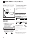
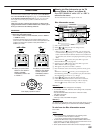
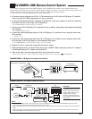
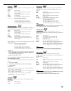
CONNECTIONS 1: IR Signal Transmitter Connection
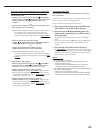
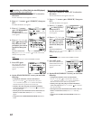
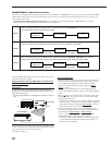
CONNECTIONS 2: AV COMPU LINK Connection
1. If you have already plugged your VCR 1 (VCR connected to the VCR 1 jacks), DVD player, TV, and this
receiver into the AC outlets, unplug their AC power cords first.
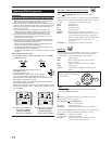
2. Connect the IR signal transmitter (supplied) to the IR OUT on the rear, and place it so that it is aimed at
the remote sensor(s) on the target video component(s).
• See “CONNECTIONS 1” below (and page 17 for details).
3. Connect your VCR 1, DVD player, TV, and this receiver as follows, using cables with monaural mini-plugs
(not supplied).
• See “CONNECTIONS 2” below.
4. Connect the audio input/output jacks on VCR 1, DVD player, TV, and this receiver using the cables with
RCA pin plug.
• See pages 13 to 15.
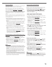
5. Connect the video input/output jacks on VCR 1, DVD player, TV, and this receiver, using the cables with
RCA pin plugs, with S-video plugs or with component video plugs.
• See “CONNECTIONS 3” on the next page (and pages 13 to 15 for details).
6. Plug the AC power cords of the components into the AC outlets.
7. When turning on the TV for the first time after the AV COMPU LINK connection, turn the TV volume to
the minimum using the TV volume control on the TV.
8. Turn on the other connected components first, then turn on this receiver.
• When turning on the VCR 1, use the remote control supplied with this receiver—press VCR 1 (STANDBY/ON).
COMPU
LINK-4
(SYNCHRO)
AV
COMPU
LINK-
TEXT
COMPU
LINK
IR
OUT
IR
IN
CTRL
OUT
+12V
10mA MAX
AV
COMPU LINK
VHS
AV
COMPU LINK
AV
COMPU LINK
EX
DVD
AV
COMPU LINK III
Notes:
• The AV COMPU LINK remote control system cannot control the DBS tuner connected to the TV SOUND/DBS IN jacks, and video
components connected to the VIDEO and VCR 2 IN jacks on the receiver.
• When connecting only the VCR 1 or DVD player to this receiver, connect it directly to the receiver using a cable with the monaural mini-
plugs.
• When connecting the receiver and the TV with AV COMPU LINK EX terminal by using the component video cables, you cannot use
Automatic Selection of TV’s Input Mode (see page 70).
VCR 1
DVD player
TV
RX-DP20VBK
CAUTION:
When connecting the TV with the
AV COMPU LINK remote control
system, connect the receiver to
the AV COMPU LINK EX or AV
COMPU LINK III terminal.
DO NOT connect the receiver to
the AV COMPU LINK RECEIVER/
AMP terminal.
Target video component(s)
Less than 3 m (10 feet)
At an angle of
approx. 60°
COMPU
LINK-4
(SYNCHRO)
AV
COMPU
LINK-
TEXT
COMPU
LINK
IR
OUT
IR
IN
CTRL
OUT
+12V
10mA MAX
IR signal transmitter
On the rear panel
RX-DP20VBK