


16
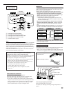
Digital Connections
This receiver is equipped with six DIGITAL IN terminals—three
digital coaxial terminals and three digital optical terminals—and one
DIGITAL OUT (optical) terminal on the rear.
• Another digital optical input terminal is located on the front panel
(see page 12).
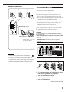
IMPORTANT:
• When connecting the DVD player, digital TV broadcast tuner, digital
VCR, or DBS tuner using the digital terminals, you also need to
connect it to the video terminal on the rear. Without connecting it to
the video terminal, you cannot view any playback picture.
• After connecting the components using the DIGITAL IN terminals,
set the following correctly if necessary:
– Set the digital input (DIGITAL IN) terminal setting correctly. For
details, see “9 Setting the Digital Input/Output Terminals—
DIGITAL IN/OUT” on page 42.
– Select the digital input mode correctly. For details, see “Selecting
the Analog or Digital Input Mode” on page 25.
Notes:
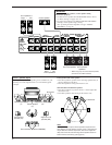
• When shipped from the factory, the DIGITAL IN terminals have
been set for use with the following components:
– 1 (coaxial) : For DVD player
– 2 (coaxial) : For CD player
– 3 (coaxial) : For digital TV broadcast tuner
– 4 (optical) : For CD recorder
– 5 (optical) : For MD recorder
– 6 (optical) : For VCR 1 (VCR connected to the VCR 1 jacks)
• When you want to operate the CD player, CD recorder, or MD
recorder using the COMPU LINK or TEXT COMPU LINK remote
control system, connect the target component also as described in
“Analog Connections” (see page 11).
• When you want to operate the VCR, TV or DVD player using the AV
COMPU LINK remote control system, connect the target
component also as described in “Analog Connections” (see pages
13 to 15).
• To use the digital source components for Zone 2, connect them
using analog connection methods as well.
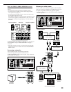
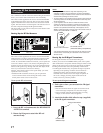
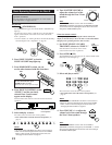
Digital input terminals
You can connect any digital components having a coaxial or optical
digital output terminal.
Digital output terminal
You can connect any digital component which have an optical
digital input terminal.
DIGITAL IN
1 (DVD)
2 (CD)
3 (TV
/DBS)
4 (CDR)
5 (MD)
6 (VCR 1)
Digital coaxial cable (not supplied)
between digital coaxial terminals
Digital optical cable (not supplied)
between digital optical terminals
PCM
/ DOLBY DIGITAL
/ DTS
DIGITAL OUT
When digital recording equipment
such as an MD recorder and a CD
recorder has a digital optical input
terminal, connecting it to the
DIGITAL OUT terminal enables you
to perform digital-to-digital
recording.
Digital optical cable (not supplied)
between digital optical terminals
Note:
The format of the digital signals transmitted through the DIGITAL OUT
terminal can be determined using the Setup Menu.
For details, see “
9
Setting the Digital Input/Output Terminals—
DIGITAL IN/OUT” on pages 42 and 43.
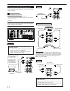
Rear view
When the component has a digital
coaxial output terminal, connect it to the
1 (DVD), 2 (CD), or 3 (TV/DBS) terminal,
using a digital coaxial cable (not
supplied).
When the component has a digital
optical output terminal, connect it to the
4 (CDR), 5 (MD), or 6 (VCR 1) terminal,
using a digital optical cable (not
supplied).
Before connecting a digital
optical cable, unplug the
protective plug.