


5
ENGLISH
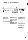
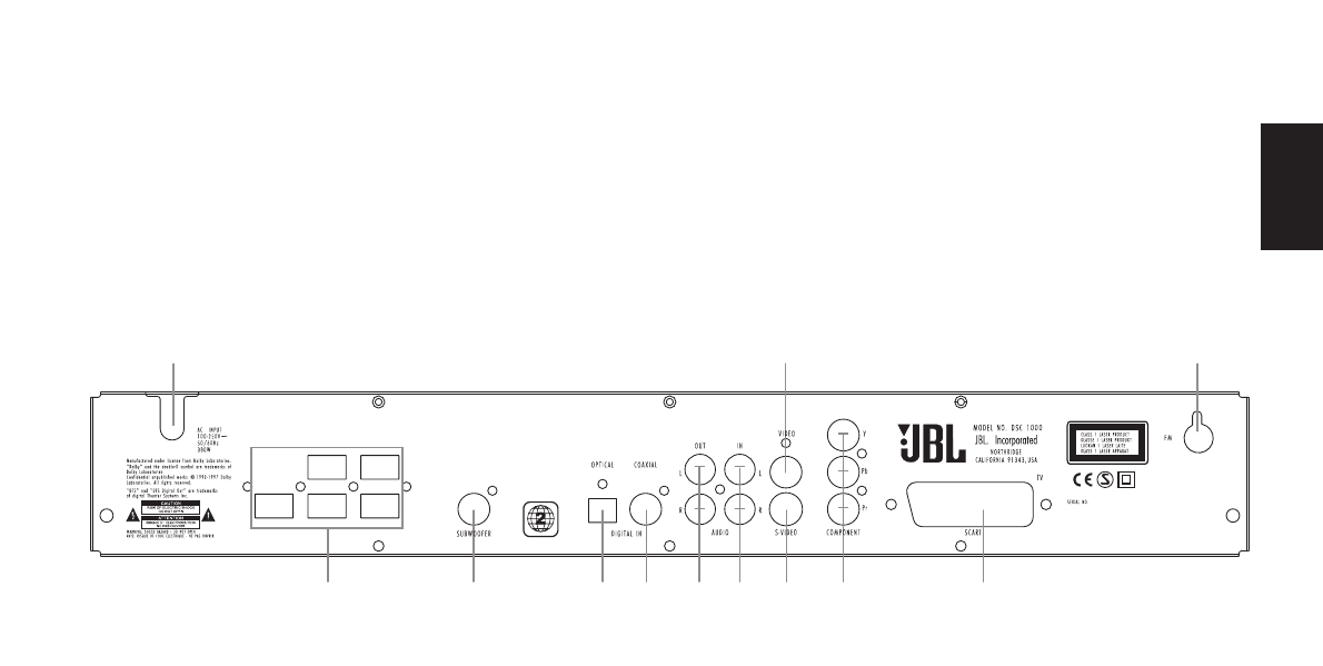
REAR PANEL CONNECTIONS
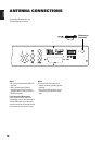
8 5 1
B 7 A 9 2 3 6 0 4
0
Component Video Outputs:
Connect to the component video
inputs of your compatible video
device.
1
FM Antenna. Connect to the
supplied FM antenna.
2
Audio Out. Optional connection to
a TV set or external audio system (also
for recording devices).
3
Audio In. Connect to a line-level
analog audio source: TV, tape player,
Minidisc, PC, etc.
4
SCART In/Out. Connect to a TV
SCART input. (SCART cable included.)
5
Video Out. Connect to a TV video
input. (Composite video cable not
included).
6
S-Video Out. Connect to a TV
S-Video input. (S-Video cable not
included).
7
Subwoofer Output. Connect to the
SUB/LFE input on the subwoofer.
8
AC Power Cord. Connect to a 230V
wall outlet.
9
Coaxial Digital Input: Connect the
coax digital output from a DVD player,
HDTV receiver, LD player, MD player,
satellite receiver or CD player to this
jack. The signal may be either a Dolby
Digital signal, DTS signal or a standard
PCM digital source. Do not connect
the RF digital output of an LD player to
these jacks.
A
Optical Digital Input: Connect the
optical digital output from a DVD
player, HDTV receiver, LD player, MD
player, satellite receiver or CD player
to this jack. The signal may be either a
Dolby Digital signal, DTS signal or a
standard PCM digital source. Do not
connect the RF digital output of an LD
player to these jacks.
B
Speaker Outputs: Connect the
colored plug at the end of the speaker
cables to the output of the
corresponding loudspeaker, marked
with the same color.