11
ENGLISH
TV, AUDIO AND POWER CONNECTIONS
Connecting the TV and
optional components
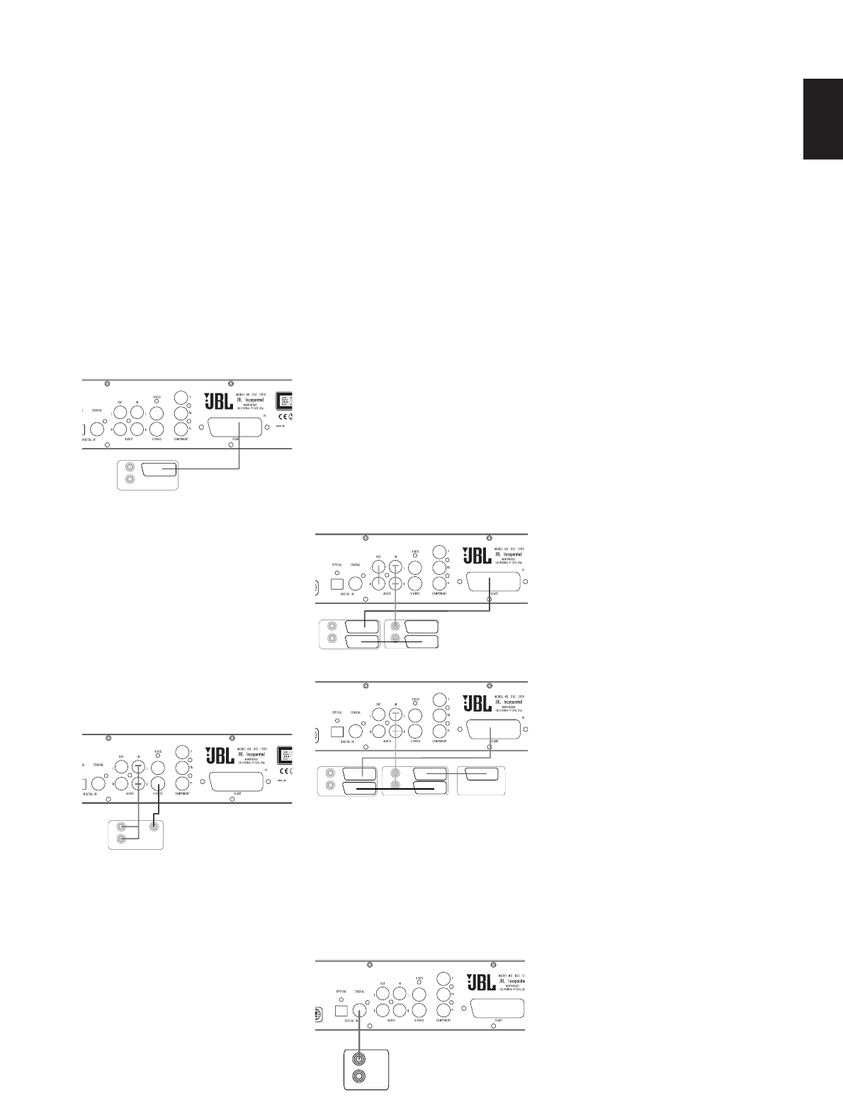
TV Connection (method 1)
- using SCART cable (included)
To view the video from DVD discs on
your TV set, connect the SCART TV Out
jack of this system to the SCART In
jack of your TV set. The same cable
also connects the audio output from
the TV to the DSC 1000 to listen to the
TV sound over the loudspeakers of
your system.
TV Connection (method 2)
- using S-Video cable
If your TV set has an S-Video Input
Jack you can connect your TV to the
S-Video Out Jack on the back of this
system (S-Videocable not included).
When connecting the DSC controller in
this manner, use the AUDIO IN Input to
carry the audio signal from your TV.
Connecting more than one video signal
output from the DSC controller will
result in degradation of the video
signal.
TV Connection (method 3)
- using composite video:
If your TV set has neither S-Video nor
SCART Input jacks, connect the Video
Out jack of this system to the Video In
jack of your TV set (Composite video
cable not included). When connecting
the DSC 1000 DVD unit in this manner,
use the AUDIO IN Audio Input to carry
the audio signal from your TV.
Connecting more than one video signal
output from the DSC 1000 DVD unit will
result in degradation of the video
signal.
Component Video Connection
(method 4)
If the video display has component
video inputs, connect the Component
Video Outputs on the DVD to the cor-
responding input jacks on your televi-
sion. If you are using a progressive
scan television or projector, you must
also change the Scan Type in the DVD
player's Video Set-Up Menu from
”Interlaced” to ”Progressive”.
Connecting VCR and Sat Decoder
(method 5 and 6)
Diagrams 5 and 6 show possible con-
nection methods for common system
configurations. These are intended as
guidelines only. Due to differences in
equipment specifications, the method
of connection of your equipment may
be different to that shown. Please
consult the Owner’s Manual of your
equipment for further guidance.
Connecting Set-top Box or Digital
Satellite Receiver (method 7) - using
coaxial digital cable
To listen to the digital multichannel
downmix from Set-top boxes or digital
satellite receivers, connect the Coaxial
Digital Out of your device to the Coaxial
Digital In on the DSC controller.
Aux Input for External Source
You may connect a line-level stereo
analog audio source such as a Sat
receiver, tape deck, phono preamp of a
record player, etc. to the controller's
rear panel AUDIO IN Input sockets to
enjoy the benefits of your DSC system
with other source components.
• VCR Connection-Audio (Cables Not
Included). To listen to the sound from
your stereo VCR through the
speakers of this system, connect the
Left/Right audio output jacks of your
stereo VCR to the Left/Right audio
input jacks AUDIO IN of this system.
• Audio Out Connections. To record the
sound of the DSC system with your
VCR or any audio recording device
(tape deck, MD, CDR and some
others.) the Audio Out jacks should
be connected to the analog Record In
jacks of the appropriate device. They
can also be connected to any audio
input on your TV to listen to the sound
of your DSC controller through the
speakers of your TV only, when the
amp in your subwoofer is turned off
and the volume of the DSC controller
has been turned down completely. If
the speakers of your JBL DSC system
are active, the volume on your TV
should be turned down.
Connecting the AC Power
Notes
• The Power Requirement is: AC 230V,
50 Hz.
• Connecting to power other than the
one listed above may damage the
system or cause abnormal operation.
• Before connecting the AC power
cord of this system to a wall outlet,
connect the speakers and other
component cables to the system.
• Connect the AC power cord of the
active subwoofer.
• Connect the AC power cords of your
TV and any optional components to a
wall outlet.
DIGITAL OUT
VCR SATELLITE DECODER
TV SET
AUDIO OUT AUDIO OUT
VCR
TV SET
AUDIO OUT AUDIO OUT
TV SET
AUDIO OUT
S-VIDEO IN
TV SET
AUDIO OUT


