DriveRack
®
25
DriveRack® User Manual
Section 3
• You are now in the Crossover module. The upper left-hand corner of the display
indicates what Crossover type is currently selected. Rotate the DATA wheel to select
the Crossover type. The letters ‘A’ or ‘B’ to the left of the crossover indicate a mono
crossover, ‘A+B’ indicates a mono summed crossover, and the letters ‘ST” indicate a
stereo crossover. Pressing and then rotating the DATA wheel lets you select the route
path (i.e. which inputs will be routed to the selected Crossover module). You can route
either Input A, Input B or a sum of the Inputs (A+B) to any mono input crossover. As
previously mentioned, a stereo crossover selection is indicated with the letters ‘ST’ (use
this selection when you want to use a stereo in/stereo out configuration). Use the PREV
PG and NEXT PG buttons to move through Outputs 1-6, configuring Crossover modules
as necessary, and then to the next module screen which will appear something like this:
GEQ
Select
Link/Unlink
<DATA> - SELECT CHARACTER
<PREV/NEXTPG> - LEFT/RIGHT
<STORE>-EDIT/<UTIL>-EXIT
NAME: Output Ch2
CONFIGURATION ERROR!
One or more outputs
have duplicated
channels.
M
6
4
2
5
3
1
M
A
B
Program 1
8
FACT
GEQ
GEQ
G
G
A
B
COMP
Select
Link/Unlink
A
B
2
N
C
F
N
S
D
D
P2X6 PP
C
C
F
1
MONO DLY 1.3
10 ms Unused
Select
Link/Unlink
A
B
D
D
1X1 FILTER
Select
Route
2
A
A
3
4
A
B
5
6
A
A
2
POST EQ
Link/Unlink
2
3
4
5
6
2P
P
P
P
P
P
LIMITER
Select
Link/Unlink
2
3
4
5
6
2L
L
L
L
L
L
MONO DLY 20 MS
810 ms Unused
Select
Link/Unlink
2
3
4
5
6
2D
D
D
D
D
D
OUTPUT CH2
Route
NAME Output Ch2
2
3
4
5
6
2
<STORE>-EDIT NAME
• You are now in the Post-Crossover PEQ module. Rotate the DATA wheel to link and
unlink these output PEQ modules as desired. Use the PREV PG and NEXT PG buttons
to move through outputs 1-6, linking and unlinking modules as desired, and then to the
next module screen which will appear something like this:
GEQ
Select
Link/Unlink
<DATA> - SELECT CHARACTER
<PREV/NEXTPG> - LEFT/RIGHT
<STORE>-EDIT/<UTIL>-EXIT
NAME: Output Ch2
CONFIGURATION ERROR!
One or more outputs
have duplicated
channels.
M
6
4
2
5
3
1
M
A
B
Program 1
8
FACT
GEQ
GEQ
G
G
A
B
COMP
Select
Link/Unlink
A
B
2
N
C
F
N
S
D
D
P2X6 PP
C
C
F
1
MONO DLY 1.3
10 ms Unused
Select
Link/Unlink
A
B
D
D
1X1 FILTER
Select
Route
2
A
A
3
4
A
B
5
6
A
A
2
POST EQ
Link/Unlink
2
3
4
5
6
2P
P
P
P
P
P
LIMITER
Select
Link/Unlink
2
3
4
5
6
2L
L
L
L
L
L
MONO DLY 20 MS
810 ms Unused
Select
Link/Unlink
2
3
4
5
6
2D
D
D
D
D
D
OUTPUT CH2
Route
NAME Output Ch2
2
3
4
5
6
2
<STORE>-EDIT NAME
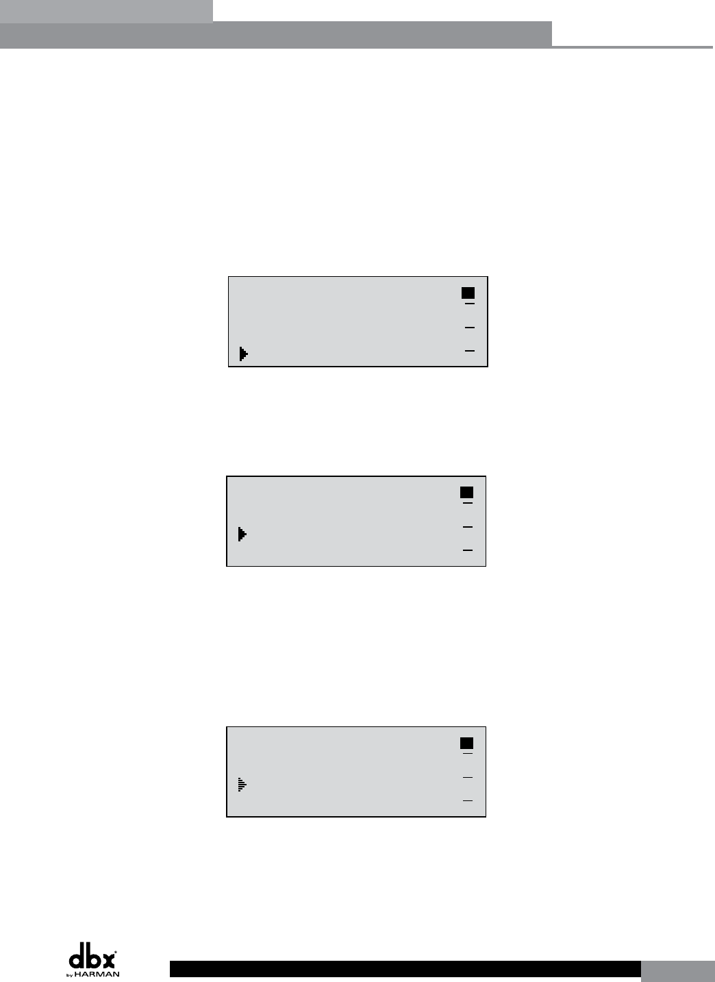
• You are now in the Post-Crossover Dynamics module. The upper left-hand corner of
the display indicates what Dynamics processor type is currently selected (i.e. Limiter
or AGC). Rotate the DATA wheel to select the Dynamics processor type. Pressing and
then rotating the DATA wheel lets you link or unlink these Dynamics modules. Note
that you can only link like type Dynamics modules. Use the PREV PG and NEXT PG
buttons to move through outputs 1-6, selecting and linking/unlinking these modules as
necessary, and then to the next module screen which will appear something like this:
GEQ
Select
Link/Unlink
<DATA> - SELECT CHARACTER
<PREV/NEXTPG> - LEFT/RIGHT
<STORE>-EDIT/<UTIL>-EXIT
NAME: Output Ch2
CONFIGURATION ERROR!
One or more outputs
have duplicated
channels.
M
6
4
2
5
3
1
M
A
B
Program 1
8
FACT
GEQ
GEQ
G
G
A
B
COMP
Select
Link/Unlink
A
B
2
N
C
F
N
S
D
D
P2X6 PP
C
C
F
1
MONO DLY 1.3
10 ms Unused
Select
Link/Unlink
A
B
D
D
1X1 FILTER
Select
Route
2
A
A
3
4
A
B
5
6
A
A
2
POST EQ
Link/Unlink
2
3
4
5
6
2P
P
P
P
P
P
LIMITER
Select
Link/Unlink
2
3
4
5
6
2L
L
L
L
L
L
MONO DLY 20 MS
810 ms Unused
Select
Link/Unlink
2
3
4
5
6
2D
D
D
D
D
D
OUTPUT CH2
Route
NAME Output Ch2
2
3
4
5
6
2
<STORE>-EDIT NAME
• You are now in the Output (Post-Crossover) Delay module. The upper left-hand corner
of the display indicates how much delay time is currently allocated to this module. The
1-6 Output indicators indicate which Output Delay module you have selected. Rotate the
DATA wheel to set how much delay time will be available to the selected Output Delay
module. Note that the actual delay time is not set at this point; the delay time can be set
Configuration Functions


