DriveRack
®
3
DriveRack® User Manual
Section 1
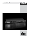
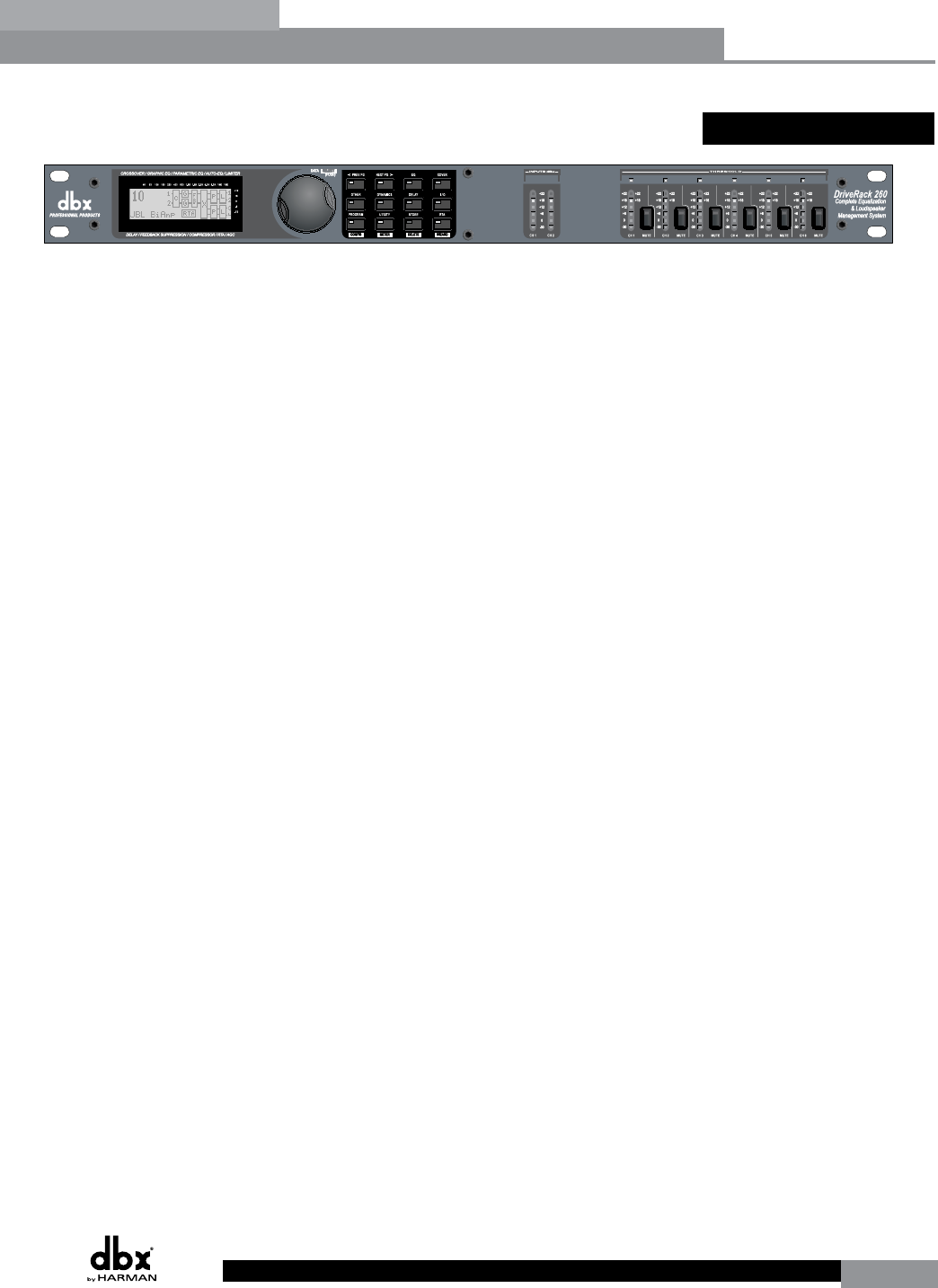
1.2 Front Panel
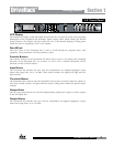
LCD Display
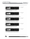
The backlit LCD display of the DriveRack 260 provides the user with all of the vital processing
information of the DriveRack 260 including: signal routing, effect block editing and Wizard
Setup functions. The display will also notify the user if any internal clipping is taking place
within the unit by displaying “CLIP” in the display.
Data Wheel
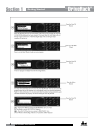
The Data wheel of the DriveRack 260 is used to scroll through the program menu, load
programs, select parameters and edit parameter values.
Function Buttons
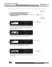
The function buttons of the DriveRack 260 allow direct access to all editing and navigating
functions of the DriveRack 260. See sections 2.1 and 2.2 for a detailed description on the
functions of each of these buttons.
Input Meters
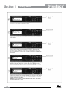
The DriveRack 260 provides the user with two independent, six segment Lightpipe™ input
meters that range from -30 to +22 dBu. These meters monitor the signal level right after the
input module.
Threshold Meters
The threshold meters indicate that the threshold level has been exceeded within the Limiter or
Auto Gain Control sections, and gain reduction may be taking place within the specific output
channel.
Output Mutes
The six output mute buttons are used for independently muting each output on all six outputs
of the DriveRack 260.
Output Meters
The DriveRack 260 provides the user with six independent six-segment Lightpipe™ output
meters that range from -30 to +22 dBu.
Getting Started


