


42
Connecting Your Components
—Continued
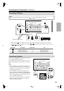
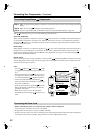
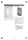
With (Remote Interactive), you can use the following special functions:
Auto Power On/Standby
When you start playback on a component connected via , if the AV receiver is on Standby, it will automatically turn
on and select that component as the input source. Similarly, when the AV receiver is set to Standby, all components
connected via will also go on Standby. This function will not work with components that are connected to an AC
OUTLET on the AV receiver.
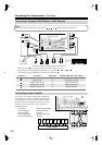
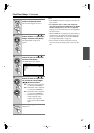
Direct Change
When playback is started on a component connected via , the AV receiver automatically selects that component as
the input source. If your DVD player is connected to the AV receiver’s multichannel input, you’ll need to press the
[Audio Selector] button repeatedly and select Multich to hear all channels (see page 81), as the Direct Change
function selects the DVD IN L/R jacks.
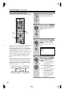
Remote Control
You can use the AV receiver’s remote controller to control your other -capable Integra/Onkyo components. You must
enter the appropriate remote control code first (see page 120). And remember to point the remote controller at the AV
receiver and not the other component.
Notes:
• Use only cables for connections. cables
are supplied with Integra/Onkyo players (DVD, CD,
etc.).
• Some components have two jacks. You can con-
nect either one to the AV receiver. The other jack is
for connecting additional -capable components.
• Connect only Integra/Onkyo components to
jacks. Connecting other manufacturer’s components
may cause a malfunction.
• Some components may not support all functions.
Refer to the manuals supplied with your other Inte-
gra/Onkyo components.
• While Zone 2 or Zone 3 is on, the Auto Power
On/Standby and Direct Change functions do not
work.
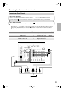
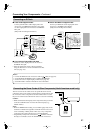
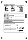
• Before connecting the power cord, connect all your speakers and AV components.
• Connect the power cord to the AV receiver’s AC INLET.
• Plug the other end of the power cord into a suitable wall outlet.
•Turning on the AV receiver may cause a momentary power surge that might interfere with other electrical equipment
on the same circuit. If this is a problem, plug the AV receiver into a different branch circuit.
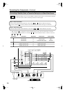
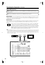
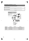
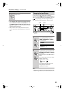
Connecting Integra/Onkyo Components
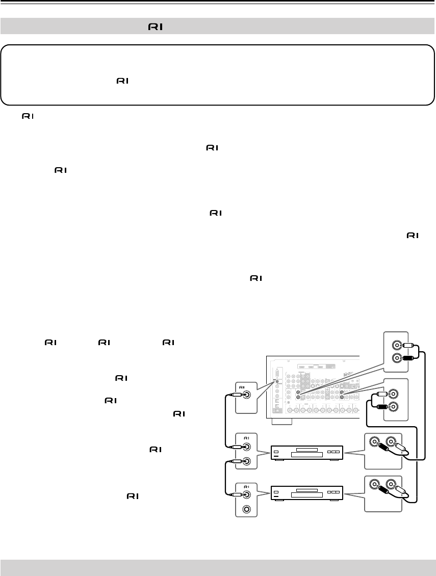
Step 1: Make sure that each Integra/Onkyo component is connected to the AV receiver with an analog audio cable
(RCA).
Step 2: Make the necessary connections (see illustration below).
Step 3: If you’re using an MD, CDR, or RI DOCK component, change the Input Display (see page 49).
RS232
DIGITAL
COAXIAL
OPTICAL
REMOTE
CONTROL
IN 1
IN 1
IN 2
IN IN IN IN
PHONO
ZONE2 R ZONE2 LFRONT R FRONT LSURR R CENTER SURR L
SURR BACK R
CD TAPE AUX 1
GAME/TV
GAME/TVCBL/SAT
CBL/SAT
AUX 1 VCR/DVR
VCR/DVR DVD
DVD
GND
IN 2
IN 3
L L
V
S
R R
ASSIGNABLE
(DVD)
(CBL/SAT)
(VCR/DVR)
(GAME/TV)
(CD)
OUT
HDMI
IN 1IN 2IN 3
ASSIGNABLE
OUT
COMPONENT VIDEO
ASSIGNABLE
IN 3
Y
CB/PB
CR/PR
IN 2 IN
1(DVD)
MONITOR
OUT 1
OUT
IN IN
OUT
IN IN FRONT FRONTCENTER
SUBWOOFER SUBWOOFER
CENTERSURR SURR
MULTI CH
PRE OUT
SURR BACK SURR BACK
AM
ANTENNA
FM75
AC INLET
Bi-AMP
SURR BACK L
Bi-AMP
ETHERNET
MONITOR OUT 2
/ZONE 2 OUT
ZONE 2ZONE 3
PRE OUT
L
R
SW
AB
IR
12V TRIGGER OUT
IN
AB
OUT
V
S
MONITOR
OUT
ZONE 2
OUT
C
LR
FRONT
DVD
L
R
IN
CD
L
R
REMOTE
CONTROL
ANALOG
AUDIO OUT
LR
ANALOG
AUDIO OUT
e.g., CD player
e.g., DVD player
Connecting the Power Cord