


12
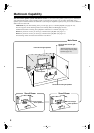
Getting to Know the AV Receiver
—Continued
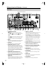
A
REMOTE CONTROL
This (Remote Interactive) jack can be con-
nected to the jack on another -capable Inte-
gra/Onkyo component for remote and system
control.
To use , you must make an analog audio connec-
tion (RCA) between the AV receiver and the other
component, even if they are connected digitally.
B
RS232
This port is for connecting the AV receiver to home
automation equipment and external controllers.
C
PHONO IN
This audio input is for connecting a turntable.
D
COMPONENT VIDEO IN 1, 2, and 3
These RCA component video inputs are for con-
necting components with a component video output,
such as a DVD player, DVD recorder, or DVR (dig-
ital video recorder). They’re assignable, which
means you can assign each one to an input selector
to suit your setup. See “Component Video Input
Setup” on page 48.
E
COMPONENT VIDEO MONITOR OUT 1
This RCA component video output is for connect-
ing a TV or projector with a component video input.
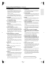
F
COMPONENT VIDEO MONITOR OUT 2/
ZONE 2 OUT
This RCA component video output is for connect-
ing a TV or projector with a component video input
located in your main listening room or Zone 2.
G
HDMI IN 1–3 and OUT
HDMI (High Definition Multimedia Interface) con-
nections carry digital audio and digital video.
The HDMI inputs are for connecting components
with an HDMI output, such as a DVD player, DVD
recorder, or DVR (digital video recorder). They’re
assignable, which means you can assign each one to
an input selector to suit your setup. See “HDMI
Input Setup” on page 46.
The HDMI output is for connecting a TV or projec-
tor with an HDMI input.
H
SIRIUS antenna (on North American model)
This jack is for connecting a SIRIUS digital
antenna, sold separately (see page 70).
I
XM antenna (on North American model)
This jack is for connecting an XM Mini-Tuner and
Home Dock, sold separately (see page 65).
J
MONITOR OUT
The S-Video or composite video jack should be
connected to a video input on your TV or projector.
K
AM ANTENNA
These push terminals are for connecting an AM
antenna.
L
ZONE 2 OUT
This composite video output can be connected to a
video input on a TV in Zone 2.
M
FM ANTENNA
This jack is for connecting an FM antenna.
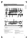
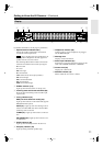
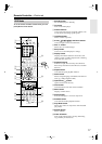
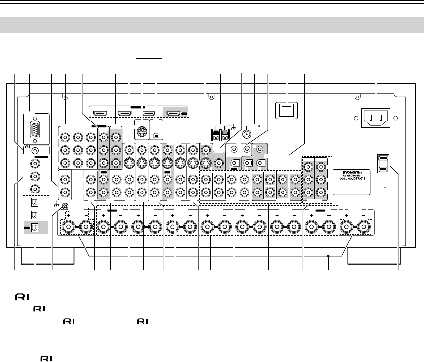
Rear Panel
RS232
DIGITAL
COAXIAL
OPTICAL
REMOTE
CONTROL
IN 1
IN 1
IN 2
IN IN IN IN
PHONO
ZONE2 R ZONE2 LFRONT R FRONT LSURR R CENTER SURR L
SURR BACK R
CD TAPE AUX 1
GAME/TV
GAME/TV CBL/SAT
CBL/SAT
AUX 1 VCR/DVR
VCR/DVR DVD
DVD
GND
IN 2
IN 3
LL
V
S
RR
ASSIGNABLE
(DVD)
(CBL/SAT)
(VCR/DVR)
(GAME/TV)
(CD)
OUT
HDMI
IN 1IN 2IN 3
ASSIGNABLE
OUT
COMPONENT VIDEO
ASSIGNABLE
IN 3
Y
C
B
/P
B
C
R
/P
R
IN 2 IN
1(DVD)
MONITOR
OUT 1
OUT
IN IN
OUT
IN IN FRONT FRONTCENTER
SUBWOOFER SUBWOOFER
CENTERSURR SURR
MULTI CH
PRE OUT
SURR BACK SURR BACK
AM
ANTENNA
FM75
AC INLET
Bi-AMP
SURR BACK L
Bi-AMP
ETHERNET
MONITOR OUT 2
/ZONE 2 OUT
ZONE 2 ZONE 3
PRE OUT
L
R
SW
AB
IR
12V TRIGGER OUT
IN
AB
OUT
V
S
MONITOR
OUT
ZONE 2
OUT
C
SIRIUS
XM
AC OUTLET
AC 120V
SWITCHED
120W 1A MAX.
60Hz
S T
8 9
64 5 J K M O21
Q
P
R
3 7
L
N
VWXZa d e fb c gYU
North American model only