


117
Zone 2 and Zone 3
—Continued
The 12V triggers A, B, and C can be used to turn on 12V
trigger-capable components automatically when they are
selected as the input source. The triggers can be set so
that they activate when a connected component is
selected as the input source for the main room, Zone 2,
Zone 3, or any combination of rooms.
When triggered, the output from a 12V TRIGGER OUT
goes high (+12 volts, 100 milliamperes max).
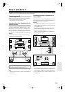
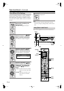
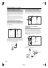
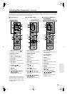
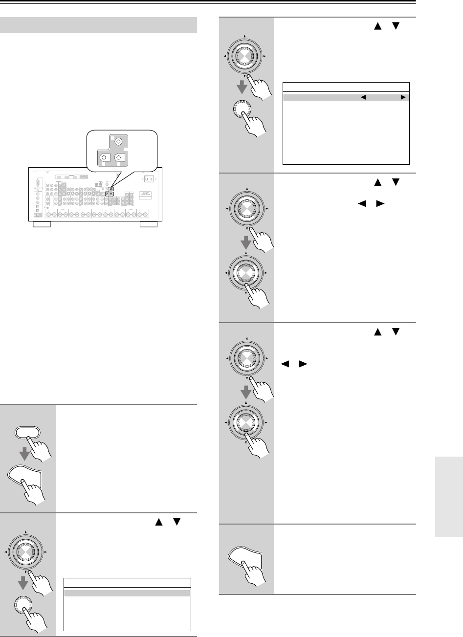
Hookup
• Use a miniplug cable to connect the AV receiver’s 12V
TRIGGER OUT A, B, or C jack to the 12 V trigger
input on a connected component.
When several components are turned on simultaneously
by using triggers A, B, and C, depending on the type of
components, a large amount of current may be drawn
momentarily. To prevent this, you can delay trigger sig-
nals A, B, and C individually. Another application for
trigger delay is eliminating the “thump” noise that’s
sometimes heard when a source component is turned on.
Delaying the trigger signal for your power amplifier so
that it’s the last component to be turned on will accom-
plish this.
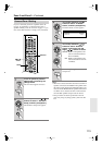
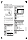
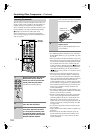
Using the 12V Triggers
1
Press the [Receiver] Remote
Mode button, followed by the
[Setup] button.
The main menu appears onscreen.
2
Use the Up and Down [ ]/[ ]
buttons to select
“6. Miscellaneous,” and then
press [Enter].
The Miscellaneous menu appears.
RS232
DIGITAL
COAXIAL
OPTICAL
REMOTE
CONTROL
IN 1
IN 1
IN 2
IN IN IN IN
PHONO
ZONE2 R ZONE2 LFRONT R FRONT LSURR R CENTER SURR L
SURR BACK R
CD TAPE AUX 1
GAME/TV
GAME/TVCBL/SAT
CBL/SAT
AUX 1 V CR/DVR
VCR/DVR DVD
DVD
GND
IN 2
IN 3
LL
V
S
RR
ASSIGNABLE
(DVD)
(CBL/SAT)
(VCR/DVR)
(GAME/TV)
(CD)
OUT
HDMI
IN 1IN 2IN 3
ASSIGNABLE
OUT
COMPONENT VIDEO
ASSIGNABLE
IN 3
Y
C
B
/P
B
C
R
/P
R
IN 2IN
1(DVD)
MONITOR
OUT 1
OUT
IN IN
OUT
IN IN FRONT FRONTCENTER
SUBWOOFER SUBWOOFER
CENTERSURR SURR
MULTI CH
PRE OUT
SURR BACK SURR BACK
AM
ANTENNA
FM75
AC INLET
Bi-AMP
SURR BACK L
Bi-AMP
ETHERNET
MONITOR OUT 2
/ZONE 2 OUT
ZONE 2ZONE 3
PRE OUT
L
R
SW
AB
IR
12V TRIGGER OUT
IN
AB
OUT
V
S
MONITOR
OUT
ZONE 2
OUT
C
AB
12V TRIGGER OUT
C
Receiver
S
e
t
u
p
Enter
Enter
6.Miscellaneous
1.Volume Setup
2.OSD Setup
3.12V Trigger A Setup
4.12V Trigger B Setup
5.12V Trigger C Setup
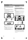
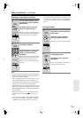
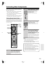
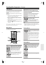
3
Use the Up and Down [ ]/[ ]
buttons to select “12V Trigger A,
B, or C,” and then press [Enter].
The 12V Trigger A/B/C Setup screen
appears.
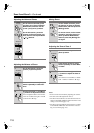
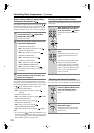
4
Use the Up and Down [ ]/[ ]
buttons to select “Delay,” and use
the Left and Right [ ]/[ ] but-
tons to select: 0 sec, 1 sec, 2 sec,
or 3 sec.
When 0 sec is selected, the trigger sig-
nal is output as soon as the input source
is changed.
5
Use the Up and Down [ ]/[ ]
buttons to select an input source,
and use the Left and Right
[ ]/[ ] buttons to select an
option.
Off
: No trigger signal is output.
A 12-volt trigger signal is output when
the connected component is selected as
the source for:
Main
: Main room.
Zone2
: Zone 2.
Main/Z2
: Main room or Zone 2.
Zone3
: Zone 3.
Main/Z3
:Main room or Zone 3.
Z2/Z3
: Zone 2 or Zone 3.
Main/Z2/Z3
:Main room, Zone 2, or
Zone 3.
6
When you’ve finished, press the
[Setup] button.
Setup closes.
Enter
Enter
6-x.12V Trigger x Setup
Delay 1sec
DVD Main/Zone2
VCR/DVR Main/Zone2
CBL/SAT Main/Zone2
TV/GAME Main/Zone2
AUX1 Main/Zone2
AUX2 Main/Zone2
TAPE Main/Zone2
TUNER Main/Zone2
CD Main/Zone2
PHONO Main/Zone2
Enter
Enter
Enter
Enter
S
e
t
u
p