


7
AM
FM
75
ANTENNA
C
DPHONO
R
L
GND
REMOTE
CONTROL
(
PLAY
)
(
REC
)
TAPE
I
N
OUT
SURROUND
SUB
WOOFER
FRONT
CENTER
R
L
R
L
R
R
L
L
R
L
R
L
V
OUT
I
N
MONITOR
OUT
I
N
I
N
S
WARNING
RISK OF ELECTRIC SHOCK
DO NOT OPEN
RISQUE DE CHOC ELECTRIQUE
NE PAS OUVRIR
AVIS
AC OUTLETS
AC 120V 60Hz
SWITCHED
TOTAL 120W 1A MAX.
AV RECEIVER
MODEL NO. DTR-5.1
DVD
VIDEO 3
VIDEO 1
R
L
V
S
SUBWOOFER
PRE OUT
FRONT
SPEAKERS
CENTER
SPEAKER
A
SURROUND
SPEAKERS
AC INLET
R
L
MULT
I
CH I
NPUT
B
FRONT
SPEAKERS
DIGITAL INPUT
COAXIAL 2
COAXIAL 1
OPTICAL 1
OPTICAL 2
I
N
VIDEO 2
DVD Player
Monitor TV
Video Cassette Recorder
VIDEO IN
S-VIDEO IN
VDP Player
AUDIO IN
S-VIDEO OUT
S-VIDEO IN
VIDEO IN
AUDIO OUT
AUDIO OUT
VIDEO OUT
VIDEO OUT
S-VIDEO OUT
AUDIO OUTPUT
DIGITAL COAXIAL OUTPUT
VIDEO OUTPUT
S-VIDEO OUTPUT
DIGITAL OPTICAL OUTPUT
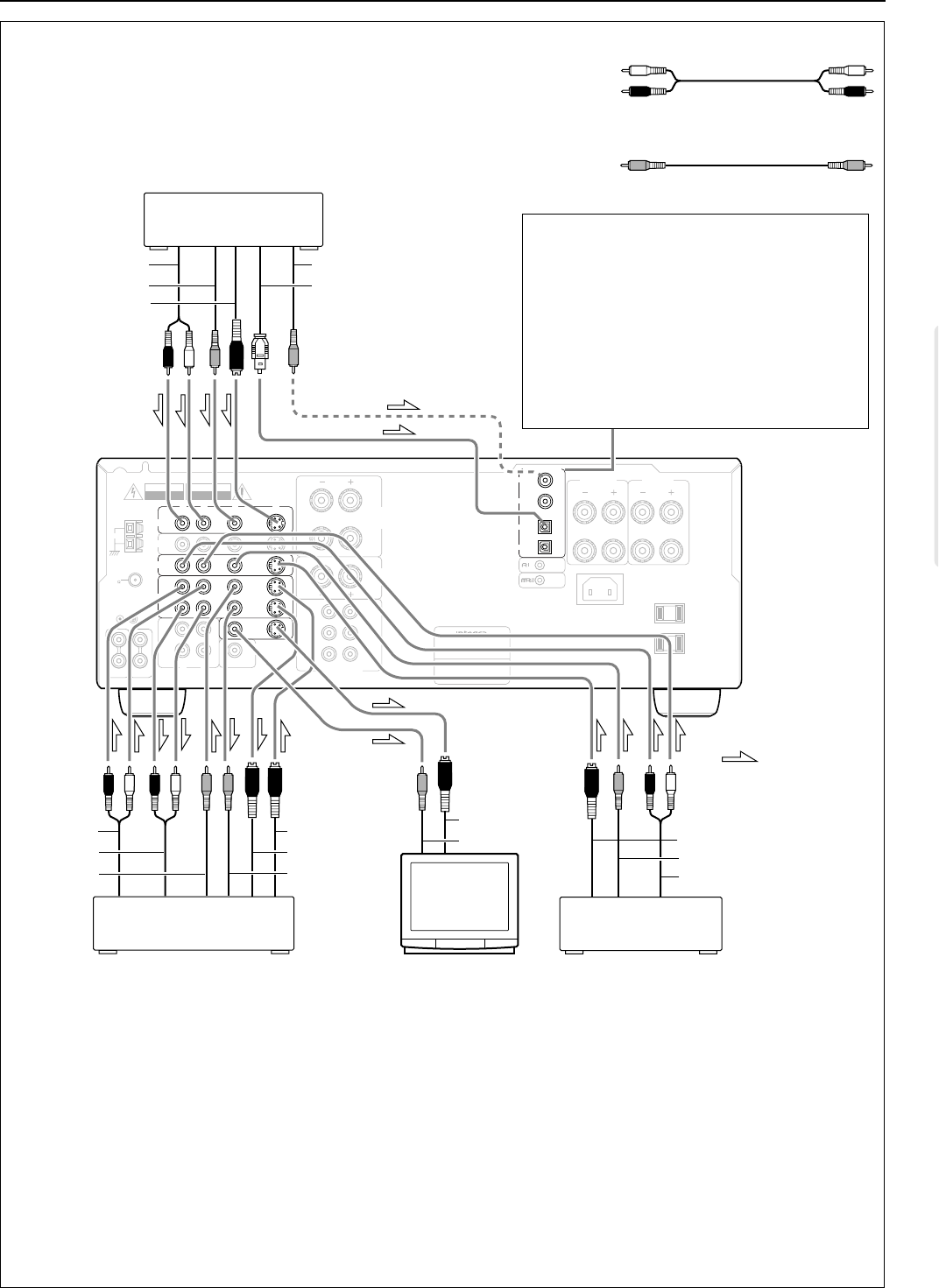
: signal flow
L (Left)
R (Right)
L
R
V (Video) V
Audio connection cable
Video connection cable
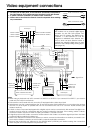
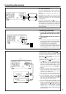
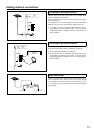
Video equipment connections
• On each pair of input jacks, a red connector (marked R) corresponds to
the right channel, and a white connector (marked L) to the left channel.
• A yellow connector (marked V) is used for video connection.
• Please refer to the instruction manual of each component when making
any connections.
Notes:
• When using a playback-only VCR, connect it to VIDEO 2 or VIDEO 3. If you connect it to VIDEO 1, you need to
make only the output connections.
• This receiver can be used with only a monitor TV equipped with a video input jack.
• Interference may be caused between the TV and this receiver. If this interference occurs, place the receiver
and the TV as far apart as possible. We do not recommend the use of a common TV/FM antenna (see
antenna section).
• A DVD or other component equipped with a digital output can be connected to this receiver. The digital con-
nection must be used in conjunction with an analog connection, because if the analog cable is discon-
nected, the audio output from TAPE OUT (REC) and VIDEO 1 OUT will not work.
• A signal input from the S-video connector will be routed to the S-video out, and the signal input from the video
connector will be routed to the video out.
• Refer to the instruction manual for the devices you wish to connect for information on whether you need to con-
nect only the S-video connector, or both S-video connector and video connector.
• Remove the protective cap attached to the DIGITAL INPUT (OPTICAL) jack before making the connection.
When this jack is not used, replace the protective cap.
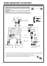
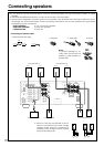
Digital audio connections
This receiver has a powerful digital signal
processor for use with DVD players, DAT
decks, and CD players. The digital inputs,
COAXIAL 1, 2 and OPTICAL1, 2 can be
assigned to individual input selector but-
tons, so when an input selector button is
pressed, the assigned digital input is used
instead of the corresponding analog input.
(See page 18.)