


6
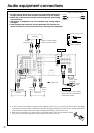
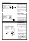
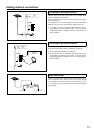
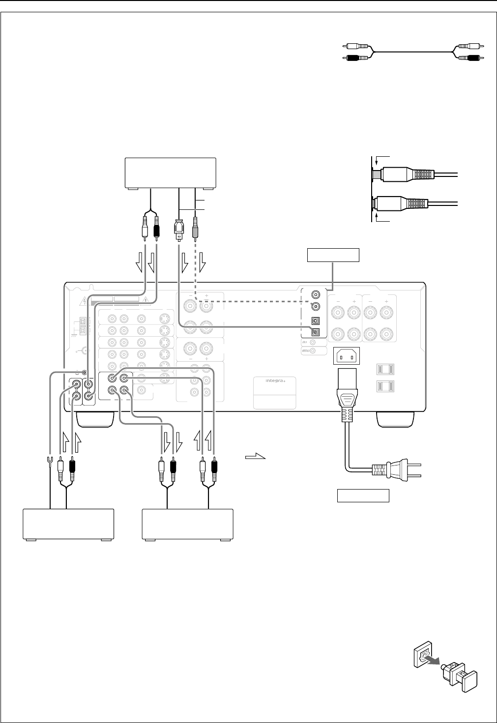
Audio equipment connections
• On each pair of input jacks, a red connector (marked R) corresponds to
the right channel, and a white connector (marked L) to the left channel.
• Please refer to the instruction manual of each component when making
any connections.
• This receiver is designed for use with turntables using moving magnet
cartridges.
• Insert the plugs and connectors securely. Remember that improper con-
nection can result in noise, poor performance, or damage to the equipment.
L (Left)
R (Right)
L
R
Audio connection cable
AM
FM
75
ANTENNA
C
DPHONO
R
L
GND
REMOTE
CONTROL
SURROUND
SUB
WOOFER
FRONT
CENTER
R
L
R
L
R
R
L
L
R
L
R
L
V
OUT
I
N
MONITOR
OUT
I
N
I
N
I
N
S
WARNING
RISK OF ELECTRIC SHOCK
DO NOT OPEN
RISQUE DE CHOC ELECTRIQUE
NE PAS OUVRIR
AVIS
AC OUTLETS
AC 120V 60Hz
SWITCHED
TOTAL 120W 1A MAX.
AV RECEIVER
MODEL NO. DTR-5.1
DVD
VIDEO 2
VIDEO 3
VIDEO 1
R
L
V
S
SUBWOOFER
PRE OUT
FRONT
SPEAKERS
CENTER
SPEAKER
A
SURROUND
SPEAKERS
AC INLET
MULT
I
CH I
NPUT
B
FRONT
SPEAKERS
DIGITAL INPUT
COAXIAL 2
COAXIAL 1
OPTICAL 1
OPTICAL 2
(
PLAY
)
(
REC
)
TAPE
I
N
OUT
R
L
INPUT
(REC)
OUTPUT
(PLAY)
Tape Deck
Turntable
CD Player
OUTPUT
(ANALOG)
DIGITAL COAXIAL OUTPUT
OUTPUT
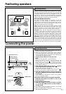
Ground
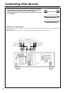
To wall
outlet
Power cable
(included)
Do not plug in the power
cable until all connections
have been made.
See page 7
See page 9
: signal flow
DIGITAL OPTICAL OUTPUT
Improper connection
Insert completely
• A DVD or other component equipped with a digital output can be connected to this receiver. The digital
connection must be used in conjunction with an analog connection, because if the analog cable is dis-
connected, the audio output from TAPE OUT (REC) and VIDEO 1 OUT will not work.
• Remove the protective cap attached to the DIGITAL INPUT OPTICAL jack before making
the connection. When this jack is not used, replace the protective cap.