


10
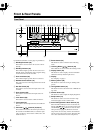
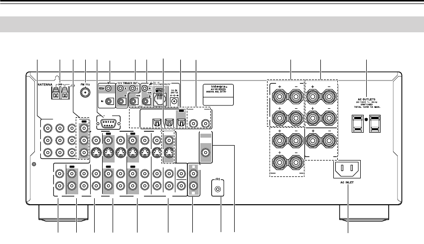
Front & Rear Panels
—Continued
For detailed information, see the pages in parentheses.
A
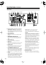
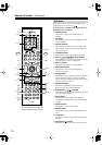
COMPONENT VIDEO IN 1, 2, 3 (27, 29, 31)
These component video inputs can be used to con-
nect AV components with component video outputs,
such as DVD players.
B
AM ANTENNA (23)
These push terminals are for connecting an AM
antenna.
C
COMPONENT VIDEO OUT (26)
This component video output can be used to con-
nect a TV or projector with a component video
input.
D
FM ANTENNA (23)
This jack is for connecting an FM antenna.
E
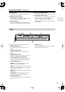
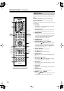
RS232 (35)
This port is for connecting the AV receiver to home
automation equipment and external controllers.
F
IR IN/OUT (67)
These jacks are for connecting the remote sensors
included with multiroom kits (sold separately).
G
12V TRIGGER OUT A/B/C (61, 67)
These jacks can be connected to the 12-volt trigger
inputs on other components. These trigger outputs
can each be assigned to an input so that when that
input is selected, a 12-volt trigger signal is output.
H
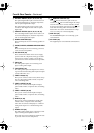
A-BUS
A-BUS is a simple, efficient, elegant audio distribu-
tion system. The wiring installation time is signifi-
cantly reduced as only a single CAT-5 wire is run to
each location. A-BUS is easy to use, reliable,
affordable, and most of all, far better sounding than
conventional auto former based volume controls.
ZONE 2 OUT:
Use CAT-5 (eight conductor
twisted) cable to connect directly from the
receiver’s A-BUS RI45 Hub to an A-BUS keypad.
Warning:
DO NOT connect A-BUS output to any computer or
network connections (i.e. ethernet). It will cause
damage to the computer or network components as
24-volt power runs on this same cable to power the
amplifier stages of the amplifier module.
IR OUT:
Another feature of the A-BUS system is
the ability to control source equipment in another
room where the A-BUS module is installed. If you
wish to control another source from the receiver at
the A-BUS keypad by remote control, connect
A-BUS or another brands’s IR emitter on the
receiver’s 40 K terminal. Then place the emitter on
the remote receiver on the front panel.
Typically, the emitter will work when you connect
with a 40 K connector. If it does not work, try a
56 K connector.
DC IN:
Connect A-Bus power supply. Do not use
any other AC Adapter on this connector as it may
cause severe damage to the receiver.
I
MONITOR OUT (26)
The S-Video or composite video jack should be
connected to a video input on your TV or projector.
Rear Panel
R
L
R
L
FRONT
SPEAKERS
CENTER
SPEAKER
R
L
R
L
R
L
ZONE 2 SPEAKERS
SURROUND
SPEAKERS
IN 1IN 2IN 3
FRONT SURR CENTER
DVD
CD
VIDEO 3 VIDEO 2 VIDEO 1
VIDEO 3 VIDEO 2
PRE OUT
VIDEO 1
IN IN IN
OUT OUT
IN IN
OUT
OUT
TAPE
SUB
WOOFER
SUB
WOOFER
MONITOR
OUT
DVD
COMPONENT VIDEO
P
B
Y
P
R
IN
OUT
IN IN IN
OUT
REMOTE
CONTROL
ZONE 2
OUT
V
S
IN 1IN
2
OPTICAL
IN1IN2
OUT
COAXIAL
DIGITAL
RS
232
R
L
4.5
UTSRQPO
KN
8
9
J
1BCD
VW
6
5 7
X
ML