22
INSTALLATION
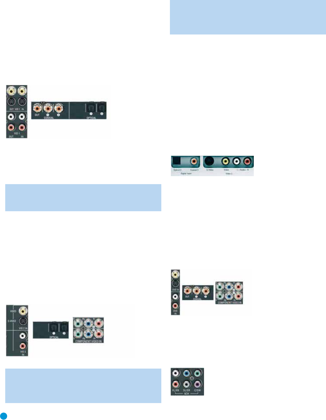
Video 1 Source
Since this source includes audio and video recording output jacks, it is
best suited to a video recorder, such as your VCR or DVR.
Referring to Table 2, connect your recorder to the Video 1 Analog Audio
inputs and outputs and to any available coaxial or optical digital audio
input (and the coax digital audio output). See Figure 19. Use either the
Video 1 S-video or composite video input and output if you wish to
make recordings. If you don’t plan on recording, you may use the
Component Video 2 inputs.
Figure 19 – Video 1 A/V Inputs and Outputs,and Digital Audio Inputs
Remember to connect the audio and video
output
jacks on your
recorder to the Video 1 or digital audio
input
jacks on the AVR, and the
audio and video
input
jacks on your recorder to the Video 1 or digital
audio
output
jacks on the AVR.
NOTE: It isn’t possible to make recordings using HDMI or compo-
nent video connections. Keep this in mind as you connect other
source devices that you may wish to make recordings from.
Video 2 Source
The Video 2 source is used only for playback. The AVR 146 remote
control is programmed to operate many brands and models of cable
and satellite television devices, and we recommend connecting your
cable or satellite set-top box to this source.
Referring to Table 2, connect your set-top box to the Video 2 Analog
Audio inputs and to the Optical 1 Digital Audio input. If possible, use
the Component Video 2 inputs. Otherwise, connect the set-top box’s
S-video or composite video output to the matching Video 2 video input.
See Figure 20.
Figure 20 – Video 2 A/V, DIgital Audio and Component Video Inputs
NOTE: If you receive your television programming using your
TV with an antenna or direct cable connection, connect the TV’s
analog and optical digital audio outputs (if available) to the Video
3 Analog Audio inputs and to one of the front-panel digital audio
inputs.
Do not
connect any video output on the television set
to any video input on the receiver. See Step Five for information
on connecting the receiver’s video monitor outputs to the
television.
Video 3 Source
The Video 3 source is used only for playback. It is also generally
reserved for components that are only temporarily connected to the
receiver, such as cameras and game consoles, although the remote is
preprogrammed to operate a TV when the Video 3 source is selected.
When not in use, you may place the supplied covers over the front-
panel Video 3 jacks for a cleaner appearance. Simply snap the covers in
place. When you wish to use the jacks, gently press on the left side of
each cover to pivot it out for removal.
Referring to Table 2, connect your camera or game console to the
Video 3 Analog Audio inputs and to either the Coaxial 3 or Optical 3
digital audio input. See Figure 21. If possible, use the Component Video
2 inputs. Otherwise, connect the device’s S-video or composite video
output to the matching Video 3 video input.
Figure 21 – Video 3 A/V and Digital Audio Inputs
DVD
The DVD source is used for a DVD player. If you have a multichannel
device, such as a Blu-ray Disc or HD-DVD player, connect it to the
DVD source.
Referring to Table 2, connect your DVD player to the DVD Analog
Audio inputs and to the Coaxial 1 Digital Audio input. If possible, use
the Component Video 1 inputs. Otherwise, connect the DVD player’s
S-video or composite video output to the matching DVD video input.
See Figure 22.
Figure 22 – DVD A/V, digital Audio and Component Video Inputs
If your DVD player plays high-resolution audio discs such as SACD or
DVD-Audio or when an HD-DVD or Blu-ray Disc player is used, connect
the 6-channel analog audio outputs on the DVD player to the 6-channel
analog audio inputs on the receiver in order to enjoy these discs to their
fullest. See Figure 23.
Figure 23 – 6-Channel Analog Audio Inputs
AVR146-OM.qxd 2/5/07 3:59 PM Page 22


