System Configuration
17
AVR65 120 volt Rev (C) 10/6/98
System Setup
Once the speakers have been placed in the
room and connected, the final step in the
setup process is to enter the settings that
configure the AVR65’s bass management
system for the type of speakers used in
your system, the calibration of the output
levels and the delay times used by the sur-
round sound processor. Before proceeding
further, this is a good time to review the
installation section of the manual to
make certain that all connections are
properly made.
You are now ready to power up the AVR65
to begin these final adjustments.
1. Plug the Power Cable fito an
unswitched AC outlet.
2. Press the Main Power Switch 1
in so that it latches in with the “OFF”
wording on the top of the switch
inside the front panel. Note that the
Power Indicator 3 will turn
amber, indicating that the unit is in
the Standby mode.
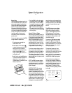
3. Install the four supplied AAA batteries
in the remote as shown. Be certain to
observe the (+) and (
–
) polarity
indicators shown in the bottom of the
battery compartment.
4. Turn the AVR65 on either by pressing
the System Power Control 2on
the front panel, or via the remote by
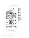
first pressing the AVR Selector a,
and then pressing the Power button
c. The Power Indicator 3 will
turn green to confirm that the unit is
on, and the Information Display ˝
will also light up.
Using the On-Screen Display
While configuring the AVR65 so that it is
properly matched to the specific speakers
in your system, as well as when setting
other system parameters, you may find it
helpful to take advantage of the unit’s
on-screen display system. These easy-to-
read displays give you a clear picture of
the current status of the unit, and make
it easy to see which speaker, delay, input
or digital selection you are making.
To view the on-screen displays, make cer-
tain you have made a connection from
the TV Monitor Video Out jack ‡on
the rear panel to the video input of your
TV, projector or display device. In order to
view the displays, the video source must be
selected as described in the instructions for
the video display.
NOTE: The AVR65’s on-screen displays
may only be viewed when the standard,
composite video output is in use. The dis-
plays are NOT visible when the S-Video
signal is displayed.
IMPORTANT NOTE: When viewing
the displays on a projection TV it is
important that they not be left on the
screen for an extended period of time. As
with any video display, but particularly
with projectors, constant display of a static
image such as these menus or video game
images may cause the image to be perma-
nently “burned in” to the CRT. This type
of damage is not covered by the AVR65
warranty, and may not be covered by the
projector TV set’s warranty. Please consult
the owner’s manual for your video display
for specific information about image
burn-in.
The AVR65 has two on-screen display
modes, “semi-OSD” and “full-OSD”.
When making configuration adjust-
ments, it is recommended that the full-
OSD mode be used. This will place a
complete status report or option listing
on the screen, making it easier to view
the available options.
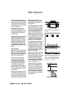
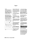
To view the full-OSD screens, press the
OSD button o three times. The first
press will bring up the semi-OSD mode
and the second press will turn that mode
off. The third press will call up the full-
OSD display (Figure 1).
The display will appear any time a
change is made to the settings or fea-
tures, and it will automatically follow the
command pattern of remote or front
panel instruction. It is not necessary to
use any other navigation buttons to use
the AVR65’s On-Screen Display system.
Note that the full screen displays will
time-out after 30 seconds. However, the
on-screen display used with the channel
output level adjustments will remain on
the screen as long as the settings are
being changed. This display must be
manually turned of by pressing the OSD
button o.
Figure 1
AUDIO SOURCE :DVD
VIDEO SOURCE :DVD
AUDIO INPUT :ANALOG
TAPE MONITOR :OFF ON
SURR. MODE :PRO LOGIC
MULTI ROOM :OFFON
MASTER VOLUME:19DB


