


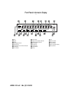

Installation and Connections
NOTE: While most speaker manufacturers
adhere to an industry convention of using
black terminals for negative and red ones
for positive, some manufacturers may
vary from this configuration. To assure
proper phase, and optimal performance,
consult the identification plate on your
speaker, or the speaker’s manual to verify
polarity. If you do not know the polarity
of your speaker, ask your dealer for
advice before proceeding, or consult
the speaker’s manufacturer.
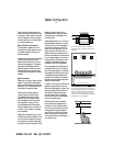
7. Connections to a subwoofer are made
via a line level audio connection from
the Subwoofer Output ª to the line
level input of a subwoofer with a built-in
amplifier. If a passive subwoofer is used,
the connection first goes to a power
amplifier, which will be connected to one
or more subwoofer speakers.
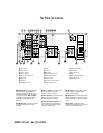
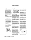
Video Equipment Connections
Video equipment is connected in a fashion
similar to audio components. Again, the
use of high-quality interconnect cables is
recommended to preserve signal quality.
1. Connect a VCR’s audio and video
Play/Out jacks to the Video 1 In jacks
£ on the rear panel. The audio and
Record/In jacks on the VCR should be
connected to the Video 1 Out jacks ¢
on the AVR65.
2. Connect the audio and video outputs
of a satellite receiver, cable TV converter
or television set or any other video source
to the Video 2 In jacks fl.
3. Connect the audio and video outputs
of a DVD or laser disc player to the DVD
jacks ¶.
4. Connect the TV Monitor Out ‡
jacks on the receiver to the video
input of your television monitor or
video projector.
NOTE: The AVR65 will accept both stan-
dard (composite) or S-Video signals.
However, it will not convert signals from
one video format type to the other.
System and Power Connections
The AVR65 is designed for flexible use
with external control components and
power amplifiers. These connections are
easy to make during an initial installa-
tion, or at a later date should you choose
to upgrade your system.
Remote Control Extension
If the receiver is placed behind a solid or
smoked glass cabinet door, the obstruc-
tion may prevent the remote sensor from
receiving commands. In this event, an
optional remote sensor may be used.
Connect the output of the remote sensor
to the Remote Cont. In jack a.
If other components are also prevented
from receiving remote commands, only
one sensor is needed. They may use this
unit’s sensor or a remote eye by running
a connection from the Remote Cont.
Out
jack b to the Remote In jack on
Harman Kardon or other compatible
equipment.
External Audio Power Amplifier
Connections
If desired, optional external power audio
power amplifiers may be used with the
AVR65. Connections to these amplifiers
are made by using audio interconnect
cables connected to both the Preamp
Outputs •
on the rear panel and
the audio input jacks of the external
amplifiers.
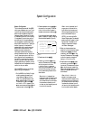
External Audio Decoder Connection
To provide for the ultimate flexibility, the
AVR65 may be used in conjunction with
optional, external decoders for digital
audio systems other than the AVR65’s
own built-in Dolby Digital and DTS
decoding system. If an external decoder
is used, connect the output jacks of the
decoder to the 6-Channel Direct inputs
∞, making sure to match channels.
These jacks may also be used for connec-
tions to devices such as DVD players or
High Definition Television (HDTV) sets
or decoders that feature built-in digital
surround decoders. Although the digital
decoding system in the AVR65 will typically
provide audio performance that is superior
to other decoders, you may use these jacks
to provide an additional 6-channel input
for connection to a DVD player or HDTV
set with a built-in decoder and discrete
6-channel analog outputs.
AC Power Connections
This unit is equipped with two accessory
AC outlets. They may be used to power
accessory devices, but they should not be
used with high-current draw equipment
such as power amplifiers. The total power
draw may not exceed 50W to each outlet.
The Switched › outlet will receive
power only when the unit is on. This is
recommended for devices that have no
power switch, or a mechanical power
switch that may be left in the “ON”
position.
NOTE: Devices with electronic power
switches may only go into a Standby
mode when plugged in here.
The Unswitched ‹ outlet will receive
power as long as the unit is plugged into
a powered AC outlet.
Finally, when all connections are com-
plete, plug the power cord into a non-
switched120-volt AC wall outlet. You’re
almost ready to enjoy the AVR65!
15
AVR65 120 volt Rev (C) 10/6/98